
Cable tray plans in CAD must make a spatial pathway understandable in a flat drawing. Clear geometry, elevation references, transition symbols, route identifiers, and coordinated supporting views help readers follow the system without mistaking schematic intent for verified installation detail.
This reference explains how to organize cable tray information for readable plans and reliable drawing coordination. Project-specific tray selection, support design, clearances, penetrations, and equipment interfaces still require review against the applicable design documents and field conditions.
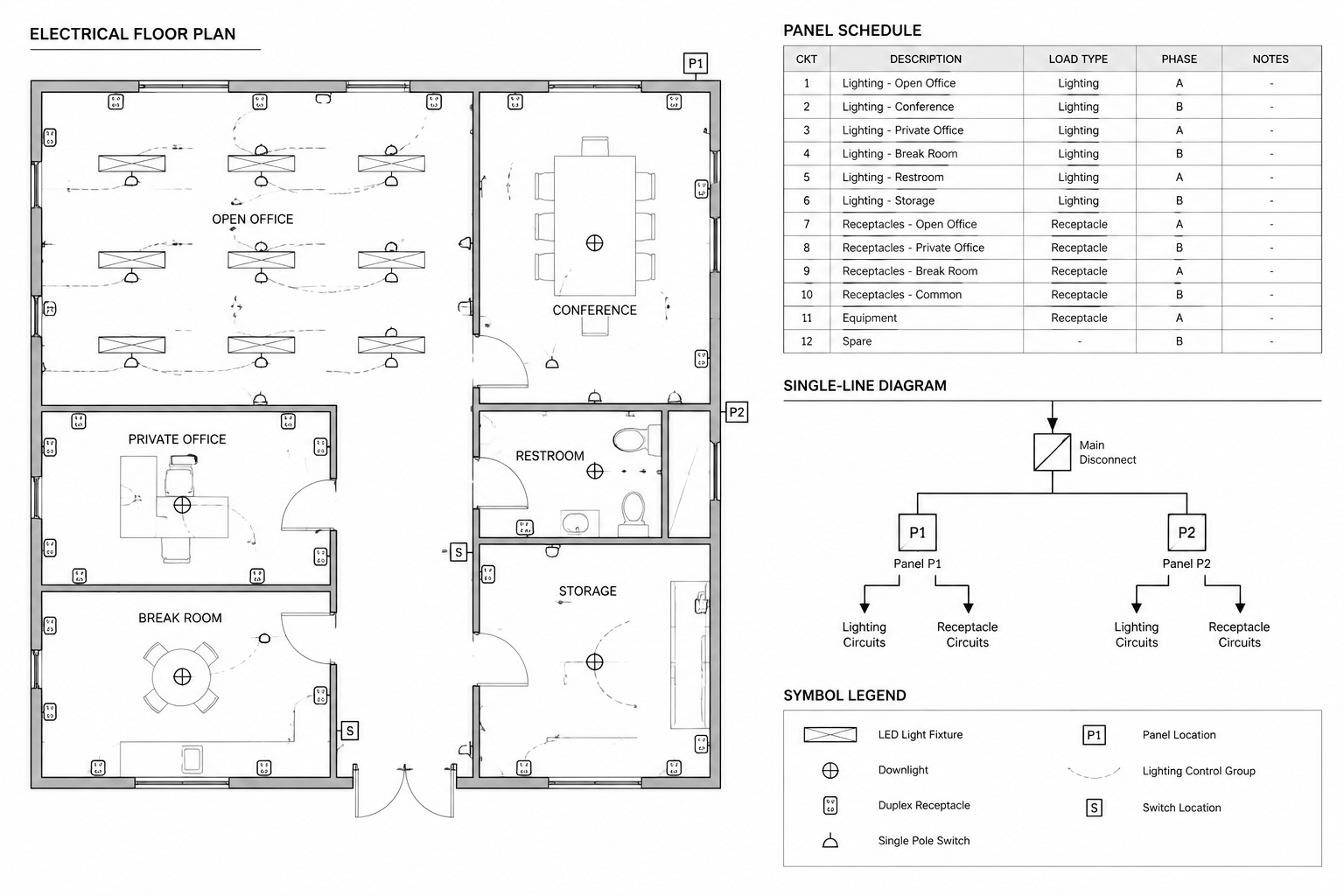
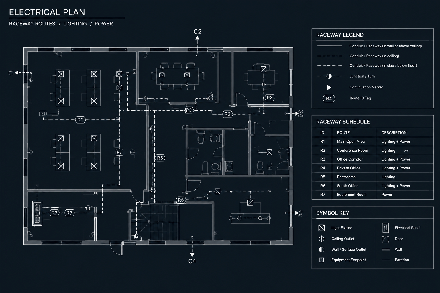
Cable tray plans translate a three-dimensional pathway system into drawings that installers, engineers, coordinators, and other disciplines can understand. A useful plan must communicate more than a line between two rooms. It should identify the tray system, show where its route changes, indicate relevant elevations, and direct readers to sections or details where plan geometry is not enough.
The challenge is balancing completeness with readability. Showing every edge, fitting, support, cable group, and overhead obstruction on one plan can make the drawing difficult to use. Showing only a centerline, however, may hide important width, access, or routing conflicts. A controlled drafting method allows cable tray plans in CAD to remain clear while supporting detailed coordination.
Decide What the Cable Tray Plan Is Intended to Communicate
Before drafting, define the purpose of the view. A design plan, coordination plan, installation drawing, and record drawing may represent the same pathway at different levels of detail. The drawing should not imply precision that the project team has not established.
A typical cable tray plan may need to communicate:
- The general tray route and the spaces it serves
- Tray identification or system classification
- Horizontal and vertical direction changes
- Relevant elevation references
- Connections to rooms, equipment, sleeves, or riser pathways
- Transitions between tray types or configurations
- Locations that require sections, elevations, or enlarged plans
- Interfaces with conduit, cable drops, and equipment entry points
Project requirements should determine which items belong on each sheet. Avoid using a generic block or typical detail as evidence that a particular arrangement has been verified for the actual structure, equipment, or cable system.
Choose a Consistent Plan Representation
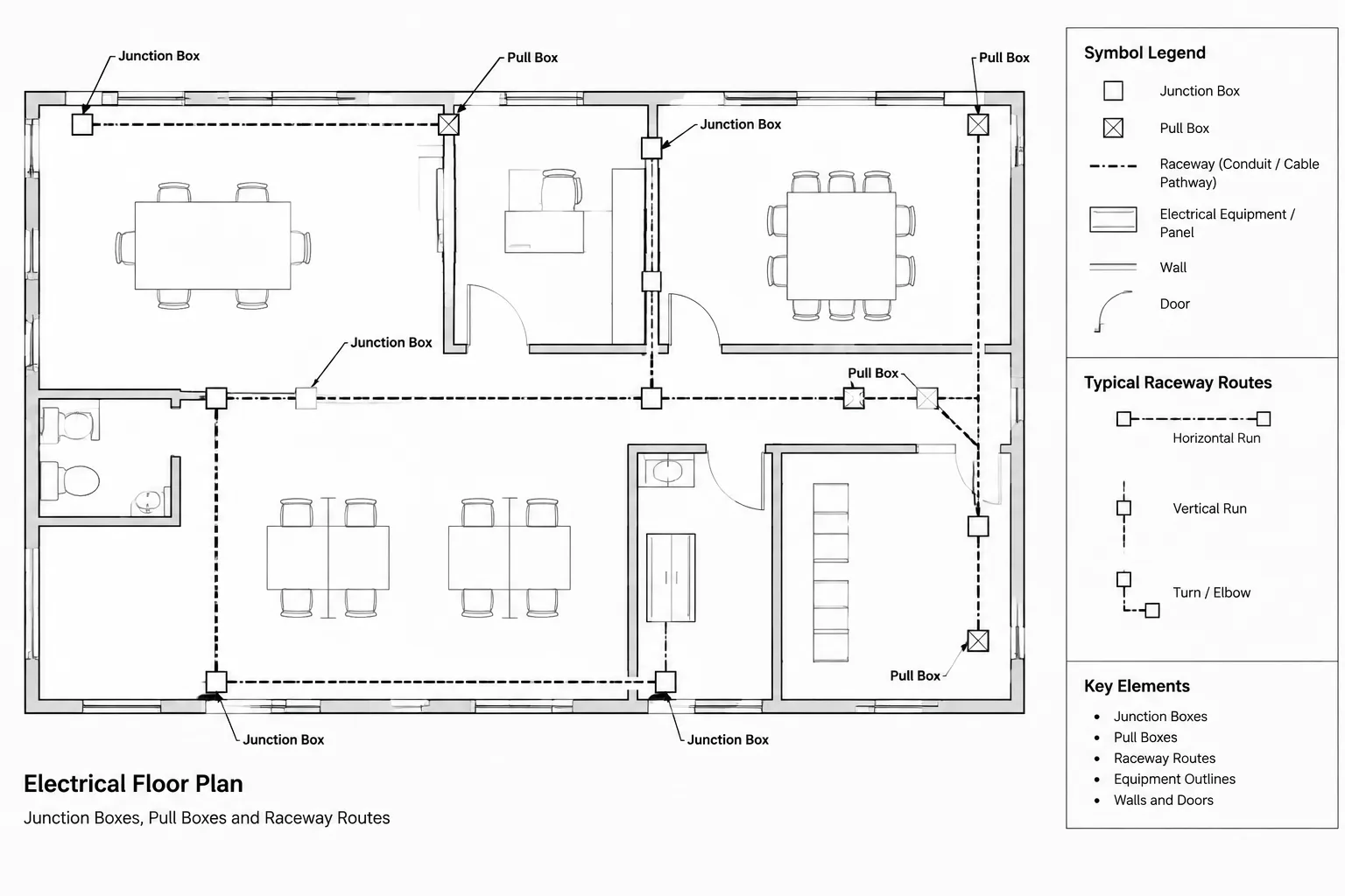
Centerline representation
A centerline is useful for schematic routing, early design studies, and plans where the tray footprint is not yet fixed. It keeps the drawing light and makes long routes easy to follow. The line should use a dedicated layer or linetype that distinguishes it from conduit, wiring, structural grids, and architectural elements.
Because a centerline does not show the tray envelope, it should be supplemented with tags or notes where width, arrangement, or spatial coordination matters. Readers should not have to infer whether a line represents the center, edge, or side of the tray.
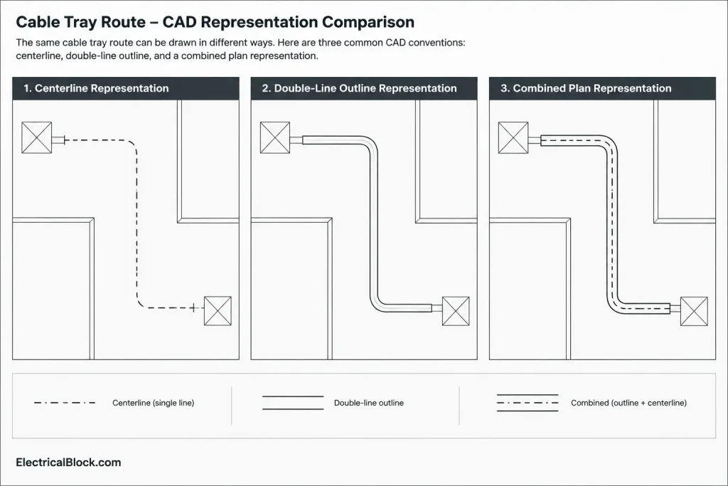
Double-line or outline representation
An outline representation shows the tray footprint more directly. It is better suited to congested spaces, equipment rooms, corridor coordination, and locations where offsets must be evaluated against other systems.
Use polylines or controlled tray components so parallel edges remain aligned through route changes. Avoid independently drawn lines that can drift apart during revisions. Centerlines may still be retained on a non-plotting or coordination layer to support alignment and measurement.
Combined representation
Many drawing sets use simplified centerlines on overall plans and tray outlines on enlarged or coordination plans. This is effective when the change in graphic convention is clearly explained in the legend and when callouts connect the two views.
Organize Cable Tray Geometry with CAD Layers
Separating tray information by function improves editing, plotting, and review. The exact layer names should follow the project CAD standard, but the information can be divided conceptually into several groups.
| Information group | Typical content | Drafting purpose |
|---|---|---|
| Tray geometry | Centerlines, edges, fittings, and transitions | Defines the pathway route and footprint |
| Tray annotation | IDs, system descriptions, elevations, and notes | Explains properties not evident from geometry |
| Vertical routing | Risers, drops, up/down symbols, and continuation markers | Identifies changes that cannot be read from plan alone |
| Coordination zones | Access envelopes or reserved pathway zones | Supports multidisciplinary review without becoming primary geometry |
| References | Section marks, detail callouts, and match references | Connects the plan to supporting views |
Do not place all tray content on one layer merely because it belongs to the same system. Separate geometry from text and reference graphics so each can be controlled independently. If different tray systems must be isolated during review, additional system-based layers or data attributes may also be appropriate.
Show Fittings and Direction Changes Deliberately
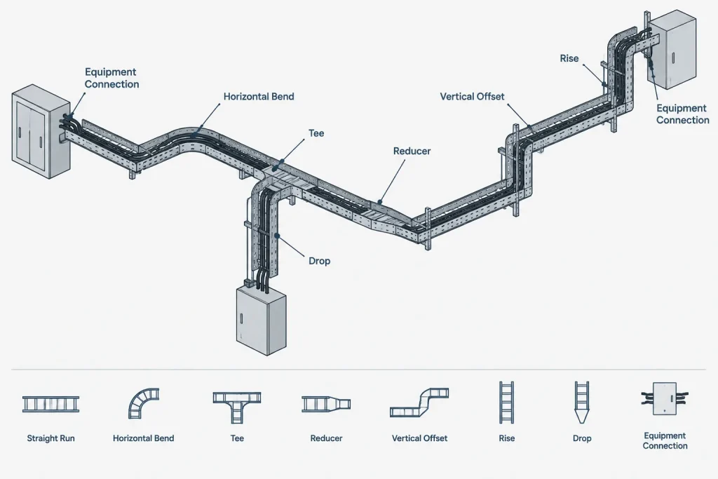
Route changes should appear intentional rather than as rough polyline corners. Horizontal bends, tees, crosses, reducers, and other transitions need recognizable geometry at the drawing’s level of detail. A plan does not necessarily need to reproduce manufacturer-specific construction, but it should show enough shape to explain connectivity and routing intent.
When using CAD blocks for fittings:
- Use insertion points that align predictably with tray centerlines or edges.
- Keep fitting orientation consistent with the direction of travel.
- Avoid mirroring blocks if doing so makes text, attributes, or asymmetrical geometry incorrect.
- Confirm that connected tray segments meet without gaps or hidden overlaps.
- Use generic symbols only until project-specific equipment and pathway selections are verified.
Reducers and offsets deserve particular attention. If a transition changes width, alignment, or elevation, show where the change begins and provide a note or supporting view when the plan cannot explain it clearly.
Document Elevation Without Overloading the Plan
Cable tray elevation is often critical to coordination, but repeated elevation text can overwhelm a long route. Use elevation labels at meaningful control points rather than placing identical notes along every segment.
Useful control points include:
- The beginning of a route
- Either side of a vertical offset
- Entries into electrical or technology rooms
- Crossings with other major building systems
- Transitions between open areas and constrained ceiling zones
- Points where a sloped or stepped route begins or ends
An elevation label should make its reference unambiguous. The drawing should state whether the value refers to the tray bottom, centerline, top, or another defined datum. It should also identify the project datum used for coordination. Do not mix reference methods without a clear explanation.
If elevations remain subject to field coordination, use wording that accurately reflects the drawing status. Avoid depicting an unverified elevation as a fixed installation requirement.
Represent Vertical Drops, Risers, and Continuations
A plan view can conceal whether a tray stops, rises, drops, or continues on another level. Use consistent up/down symbols and pair them with identifiers or cross-references. The symbol alone may be insufficient where multiple trays occupy the same area.
For each vertical transition, consider documenting:
- The tray or pathway ID
- The direction of travel
- The destination floor, room, equipment item, or drawing
- The relevant elevation change
- A reference to a riser diagram, section, or detail
At floor openings and shafts, coordinate tray geometry with sleeves, framed openings, fire-rated assemblies, and structural boundaries shown in the background. The electrical plan should identify the interface, while verified architectural, structural, and project requirements govern the final opening arrangement.
Coordinate Tray Routes with Cables, Conduit, and Equipment
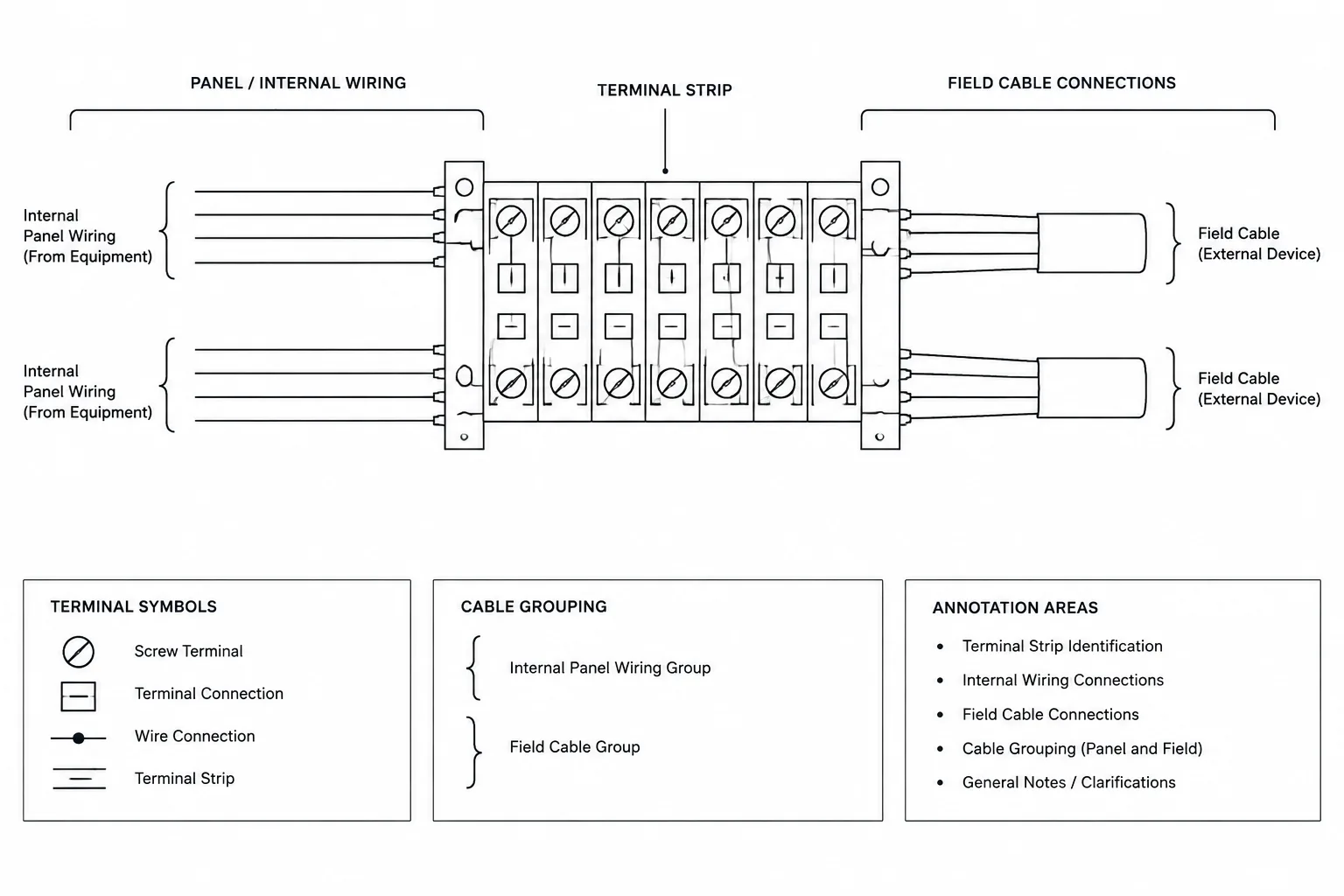
The tray plan should show how other electrical pathways enter and leave the system without turning the drawing into a full cable installation diagram. Conduit connections, cable drops, and equipment interfaces can be indicated with concise symbols and references.
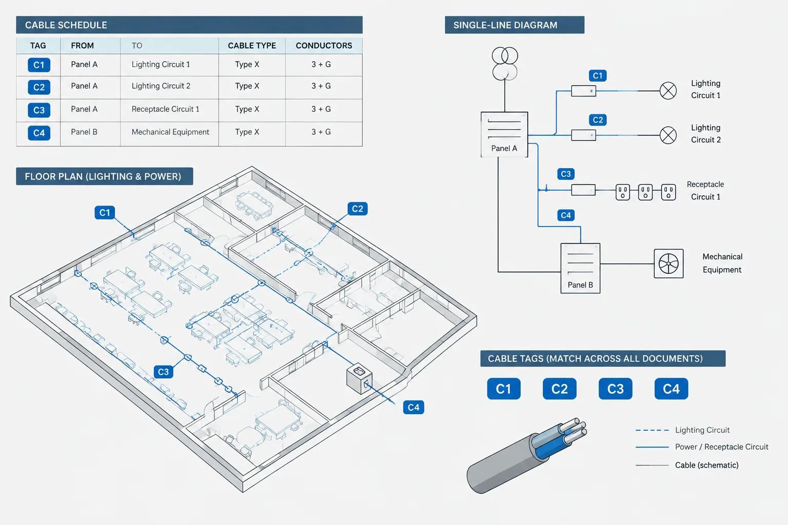
Use consistent tags to connect the plan with cable schedules, conduit schedules, equipment layouts, and diagrams. If a cable group changes tray routes, the documentation should make that transfer traceable. Do not rely solely on color because plotted drawings, exports, and field copies may be monochrome.
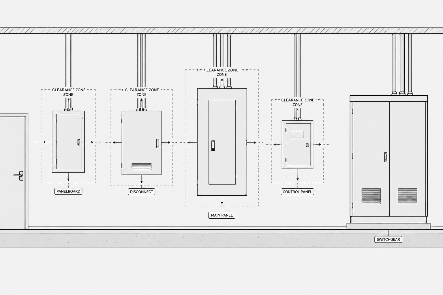
Equipment entry points should be coordinated with the equipment footprint and connection location. A tray line that merely touches an equipment outline may be mistaken for a verified connection. Use a defined termination symbol, note, elevation, or detail reference where the interface matters.
Use Sections Where Plan View Becomes Ambiguous
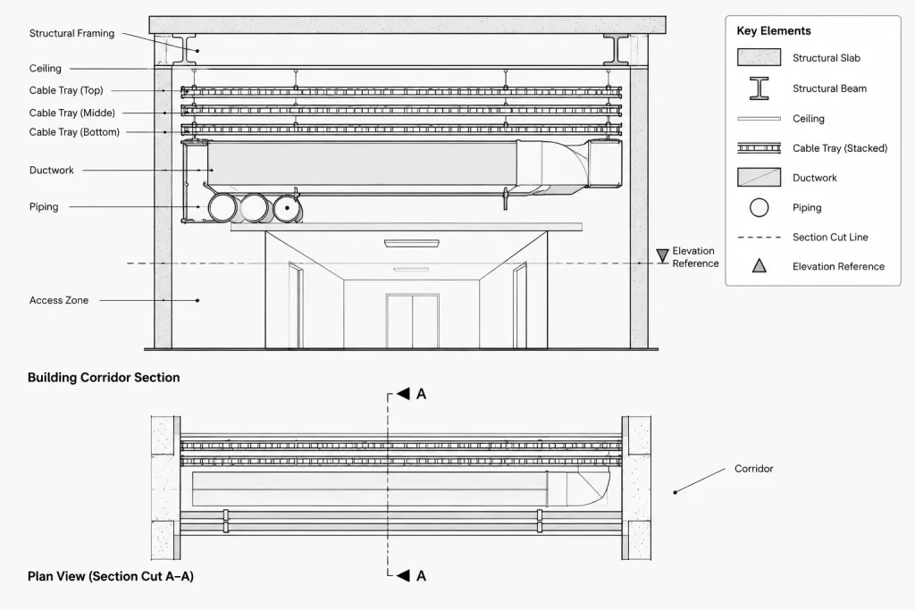
Sections are valuable at stacked routes, corridor crossings, equipment approaches, shaft entries, and other constrained areas. The plan should include a section cut with a unique reference and a clearly indicated viewing direction.
A supporting section can show:
- The relative position of parallel or stacked trays
- Tray elevations and alignment
- Nearby ceilings, beams, ducts, pipes, or access zones
- Wall or floor penetrations
- Conduit entries and cable drops
- The relationship between the route and equipment
Keep the section synchronized with the plan. If the route moves, review the section cut, section geometry, tags, and dimensions together. A section copied from another location should not be presented as project-specific unless its conditions have been verified.
Apply a Focused Quality-Control Workflow
Before issuing cable tray plans in CAD, perform a route-based review rather than checking only individual sheets. Begin at each source or pathway origin and follow the route to every destination.
- Confirm that tray IDs remain consistent across plans, sections, risers, and schedules.
- Check every tee and branch for a documented destination.
- Verify that up/down symbols have matching continuation information.
- Review elevations at offsets, crossings, and room entries.
- Look for gaps, duplicate lines, disconnected fittings, and overlapping annotations.
- Confirm that section marks point to current and correctly titled views.
- Compare tray routes with the latest architectural, structural, mechanical, and equipment backgrounds.
- Plot the sheets at their intended output size to test lineweight and text readability.
A well-drafted cable tray plan is not simply a pathway sketch. It is a coordinated navigation document that connects geometry, elevation, system identity, and supporting views. Consistent CAD conventions make the route easier to review while leaving project-specific sizes, supports, clearances, and installation details subject to the appropriate design and verification process.
Read the Drawing as a Connected Route
A cable tray plan is most useful when it can be followed continuously from origin to destination. Reviewers should be able to identify where the route begins, how branches are named, where elevations change, and which view explains any condition that is unclear in plan.
Start with the legend and drawing notes to determine whether the route is represented by a centerline, an outline, or a combination of conventions. Then follow the tray identifier through fittings, vertical transitions, match lines, enlarged plans, and referenced sections. Apparent terminations should be checked for continuation symbols, equipment interfaces, or links to another drawing.
Separate Design Intent from Coordination Status
CAD geometry can appear more precise than the information used to create it. Layer names, linework, notes, and issue status should distinguish established design intent from routes that remain under coordination. This is especially important where tray runs pass through congested ceilings, approach equipment, cross structural elements, or depend on openings supplied by another discipline.
Background files should also be treated as controlled references. When an architectural, structural, mechanical, or equipment background changes, review the entire affected route rather than only the area marked by the revision. A local change can alter downstream offsets, section locations, annotation placement, and continuation references.
Use Data and Graphics Together
Geometry explains where the tray runs, while tags and attributes explain what the geometry represents. Consistent identifiers can connect plan segments with sections, riser diagrams, schedules, and equipment layouts. Where attributes are used, verify that copied or mirrored components retain the correct system identity and orientation.
Graphic checks remain necessary even when tray objects contain data. A valid identifier does not reveal an accidental gap, an overlapping fitting, an unclear crossing, or a label obscured by background linework. Effective quality control combines route tracing, data review, reference checking, and plotted-sheet inspection.
Maintain Clear Revision Ownership
Revisions should identify whether a change affects routing, elevation, system classification, equipment connection, or only drawing presentation. When multiple disciplines participate in coordination, the drawing set should make responsibility for final geometry and interface verification clear.
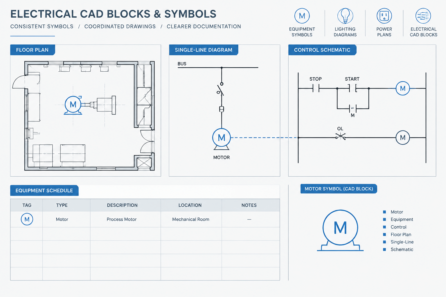
Typical details and reusable CAD blocks can improve consistency, but they should remain visibly generic unless the depicted condition has been checked for the project location. A coordinated plan communicates both what is known and where further verification is required.
Frequently Asked Questions
When should a cable tray route use centerlines instead of outlines?
Centerlines are useful for schematic routing and overall plans where the tray footprint is not fully established. Outlines are more informative where the pathway envelope, offsets, or nearby systems must be evaluated. A drawing set may use both conventions if the legend and view references explain the difference.
What should an elevation note identify?
The note should make clear which part of the tray the elevation references and which project datum is being used. Labels are most helpful at route origins, offsets, crossings, room entries, and other control points where the elevation changes or affects coordination.
How should a vertical tray transition appear in plan?
Use a consistent rise or drop symbol together with a route identifier and a continuation reference. Where plan graphics cannot show the condition clearly, direct the reader to a section, riser diagram, detail, or another coordinated view.
Why are sections important for cable tray coordination?
Plan views can hide stacked routes and vertical relationships. Sections clarify how trays relate to ceilings, structure, other building systems, penetrations, access zones, and equipment approaches.
Should cable tray plans show individual cables?
That depends on the drawing purpose. The plan may use cable-group tags or references to schedules and diagrams rather than displaying every cable. The chosen method should preserve route traceability without making the plan unreadable.
How can CAD users prevent tray fittings from becoming disconnected?
Use consistent insertion points, alignment methods, object snaps, and controlled tray components. After revisions, inspect each bend, branch, reducer, offset, and equipment interface for gaps, overlaps, or incorrect orientation.
Leave a Reply
You must be logged in to post a comment.