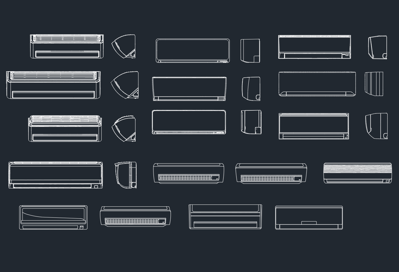
Air conditioner CAD blocks help designers represent HVAC equipment clearly in architectural, interior, and MEP drawings. A well-organized block can communicate the general location and visual form of an air-conditioning unit without requiring the equipment to be redrawn for every plan.
This resource provides Air Conditioner CAD Blocks in DWG format, covering split, window, and central air-conditioning representations. Use the drawings as drafting references and coordinate them with the project’s architectural layout, mechanical design information, and electrical documentation.
Discover high-quality Air Conditioner CAD Blocks available in DWG file format, perfect for architects, engineers, and interior designers. These CAD blocks are meticulously detailed, representing various types of air conditioning units such as split, window, and central systems. Easily integrate these blocks into your architectural or MEP projects to enhance HVAC plans. The DWG file ensures seamless compatibility with AutoCAD and other leading CAD software. Save time on your design workflow by downloading our ready-to-use Air Conditioner CAD Blocks for precise and professional project documentation.
Please log in or register to download this file.
How to use air conditioner CAD blocks
Air-conditioning blocks are most useful when the drawing needs a consistent graphical reference for equipment placement. They can support floor plans, reflected ceiling plans, interior layouts, equipment arrangements, and broader MEP coordination drawings. Before inserting a block, check its orientation, insertion point, scale, and layer behavior so that it aligns with the rest of the drawing.
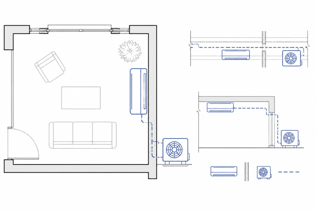
Common equipment categories
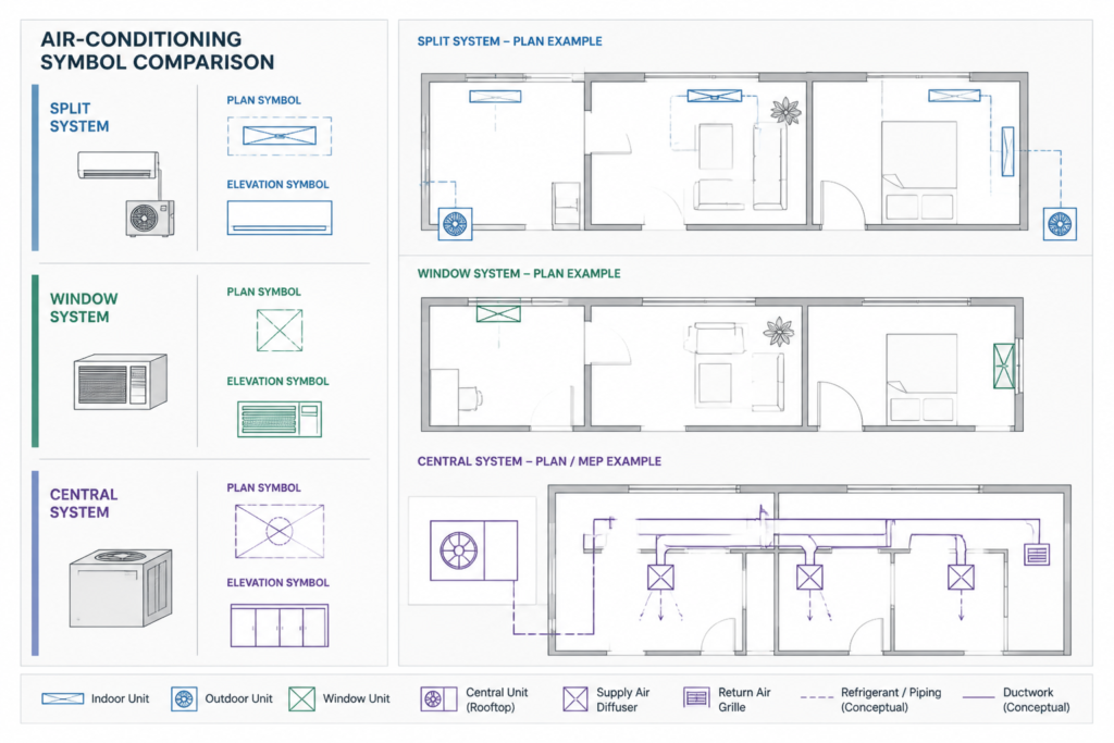
- Split units: Use these representations to show the indoor unit and its relationship to the surrounding room or architectural elements. Any outdoor equipment, routing, or connection information should be coordinated separately with the project documentation.
- Window units: These blocks can help indicate equipment positioned at or near a window opening. Confirm that the architectural drawing and mechanical information support the shown location.
- Central systems: Central air-conditioning concepts may involve equipment, distribution, and service relationships that require coordination across mechanical and architectural drawings. A CAD block is a graphical reference, not a complete system design.
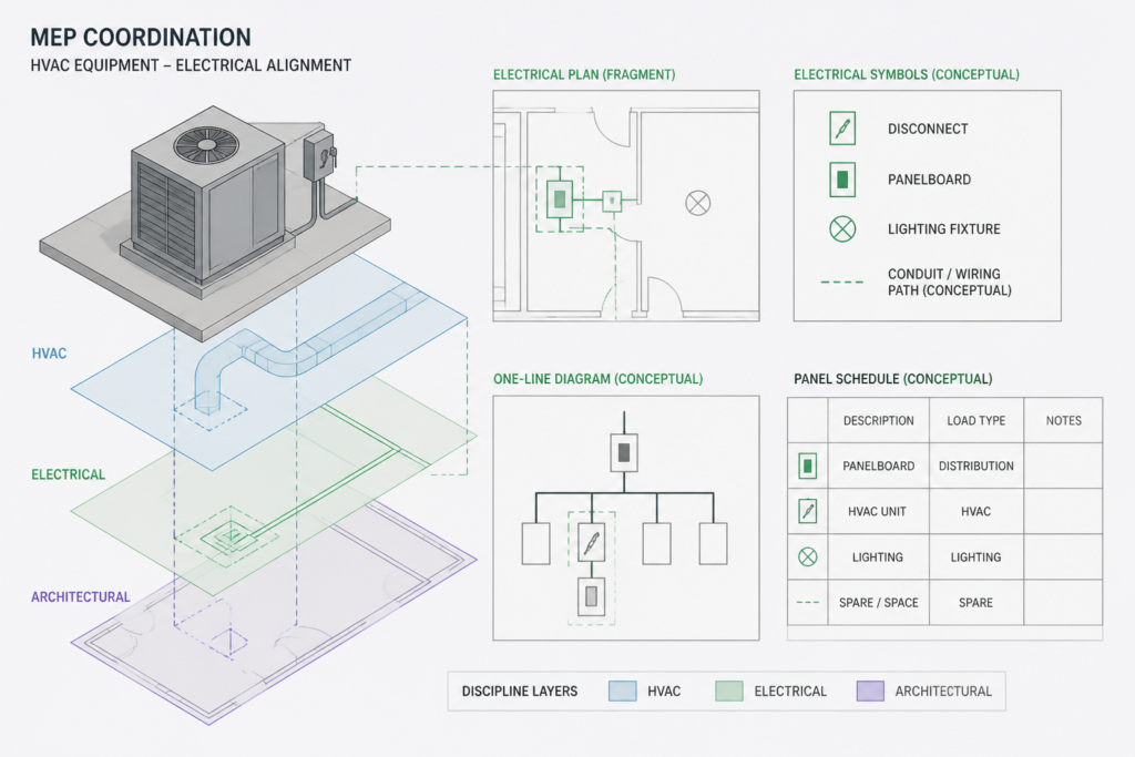
CAD and electrical coordination
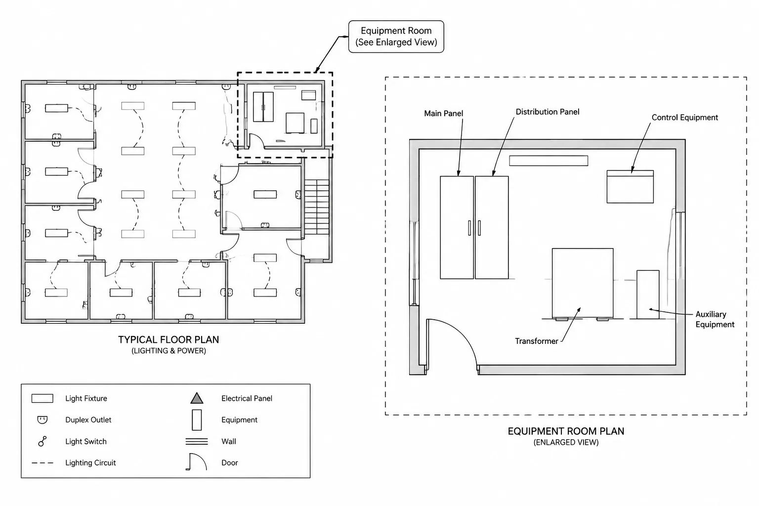
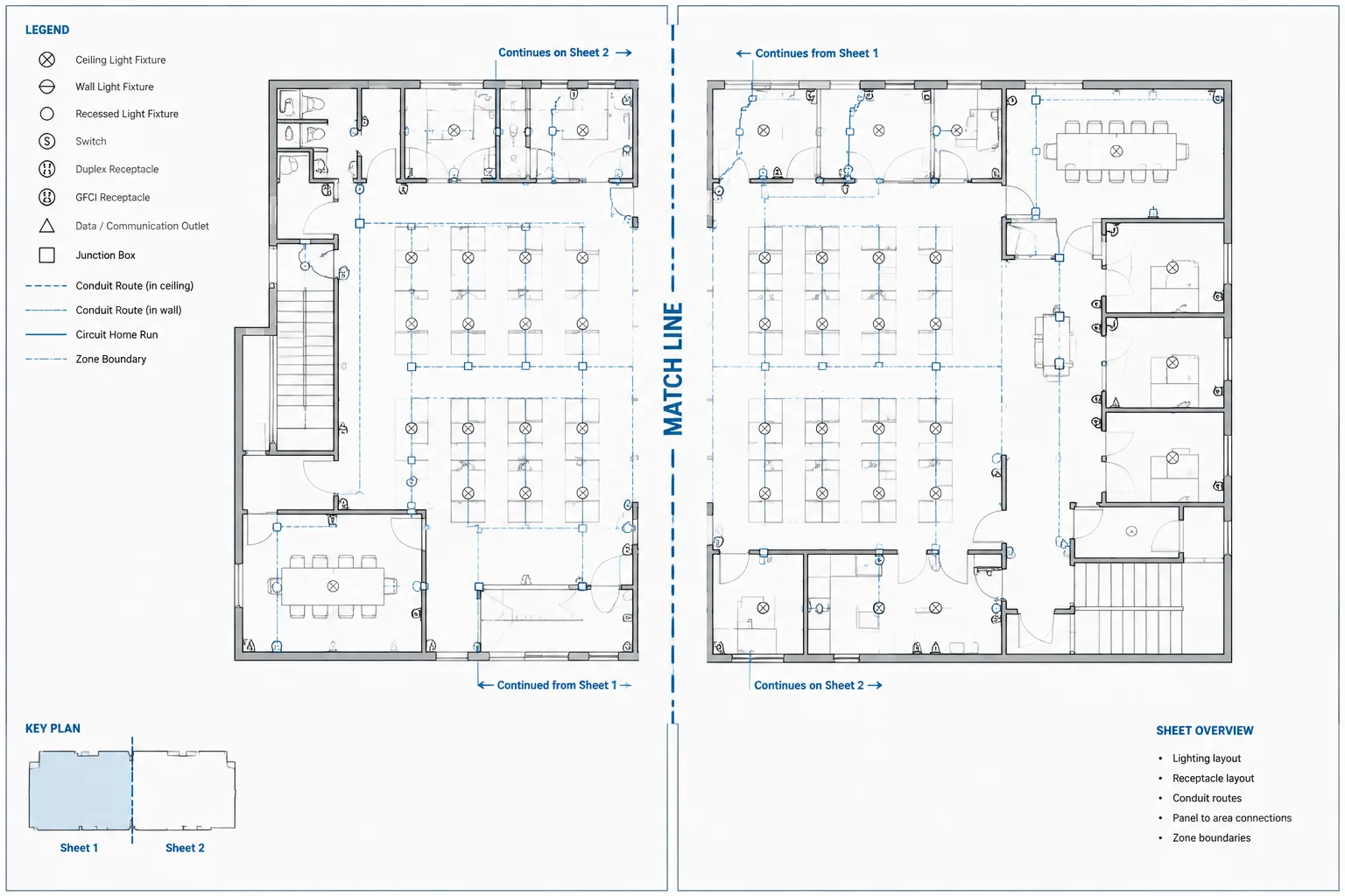
Although the blocks represent HVAC equipment, their placement may affect electrical plans, panel schedules, conduit layouts, ceiling coordination, and equipment access. Compare the HVAC drawing with relevant electrical symbols and legends, power-plan conventions, and distribution-equipment layouts. The block alone does not establish a power connection, protective-device selection, conductor arrangement, or installation requirement.
Drawing-management checklist
- Place the block on a logical HVAC or equipment layer according to the project’s CAD standards.
- Review lineweight, color, visibility, and plotting behavior in the target drawing.
- Keep architectural, mechanical, and electrical information distinguishable when several disciplines share a plan.
- Use nearby notes or tags when the project requires equipment identification or coordination status.
- Verify the block against current project information before using it for issued documentation.
Related drawing references
Air conditioner blocks are commonly reviewed alongside HVAC plan symbols, electrical plan legends, lighting and power plans, panel schedules, cable and conduit drafting, and single-line diagram concepts. Understanding these relationships makes it easier to read the equipment context without treating a visual CAD symbol as a complete engineering specification.
Frequently asked questions
What format are these air conditioner CAD blocks provided in?
The source provides the blocks in DWG format, which is intended for use with AutoCAD and other compatible CAD software.
What types of air-conditioning equipment are represented?
The collection describes split, window, and central air-conditioning units. Review each drawing before use to understand its graphical coverage and intended drafting context.
Can these blocks be used in electrical drawings?
They can support coordination between HVAC and electrical documentation, but they do not define electrical ratings, connections, protective devices, conductor sizes, or code-compliant installation details.
Are the blocks a substitute for HVAC design information?
No. A CAD block communicates graphical intent or equipment location. Final equipment selection, system layout, clearances, connections, and engineering verification must come from the applicable project documentation and responsible design professionals.
What should be checked before adding a block to a drawing?
Check the block’s orientation, scale, insertion behavior, layer assignment, lineweight, plotting appearance, and coordination with the architectural, mechanical, and electrical backgrounds.










Leave a Reply
You must be logged in to post a comment.