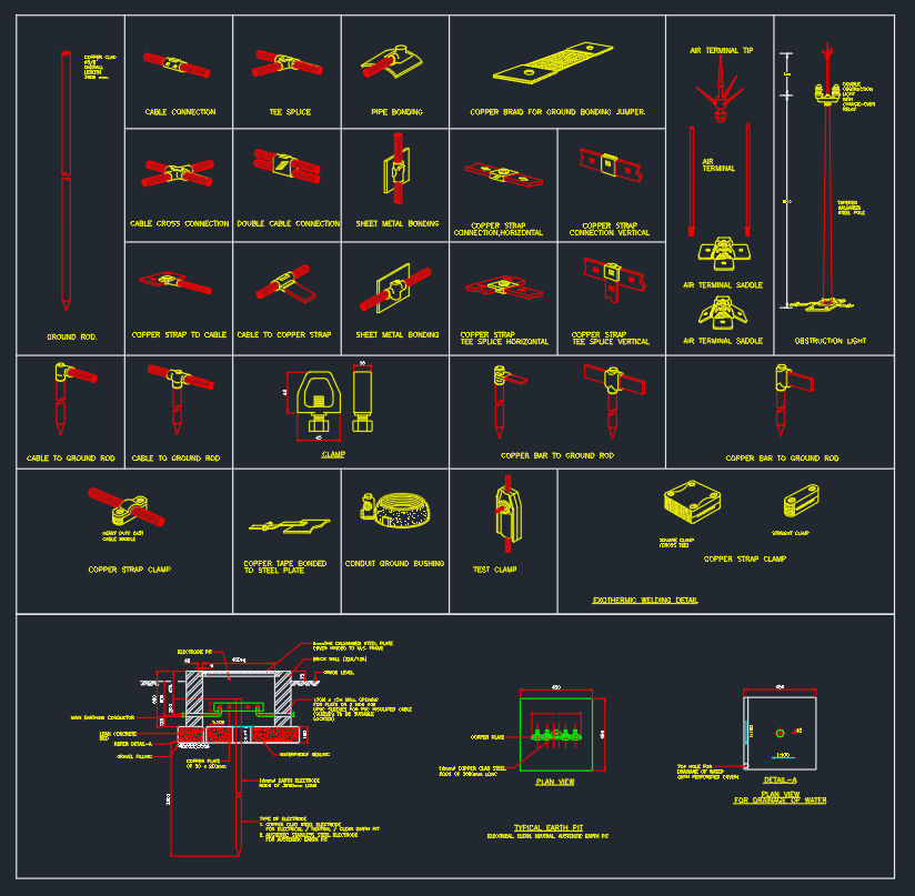
An equipment grounding conductor DWG block provides a reusable graphic for identifying grounding-related connections in electrical CAD documentation. Depending on the drawing type and office convention, it may appear in a schematic, single-line diagram, equipment detail, grounding diagram, or symbol legend.
Because grounding graphics and abbreviations can vary among firms and projects, review the block before placing it in a drawing. Confirm its geometry, insertion point, layer assignment, scale behavior, and intended meaning against the project legend and drafting requirements.
Discover a high-quality Equipment Grounding Conductor DWG file, perfect for your electrical design needs. This detailed CAD Block provides an accurate representation of grounding conductors, essential for ensuring electrical safety in residential, commercial, and industrial projects. Ideal for electrical engineers and architects, the file streamlines your design process by offering a ready-to-use symbol for equipment grounding. Fully compatible with AutoCAD and other CAD software, this Equipment Grounding Conductor DWG file can be easily integrated into your schematic diagrams and layouts, improving accuracy and compliance with electrical codes. Download and enhance your project documentation today.
Please log in or register to download this file.
What the block represents
An equipment grounding conductor establishes a grounding connection between electrical equipment and the applicable grounding path. In a drawing set, the concept may be communicated through a dedicated symbol, a conductor line, a leader note, an abbreviation, or a combination of these elements.

The CAD block is a documentation aid rather than a complete design decision. Its use does not establish conductor selection, routing, termination requirements, or compliance by itself. Those items must be determined from the approved design criteria and applicable requirements for the project.
Where it may appear in electrical drawings
- Single-line diagrams: to clarify grounding relationships between equipment and distribution components.
- Schematic diagrams: to identify an equipment grounding connection within a circuit representation.
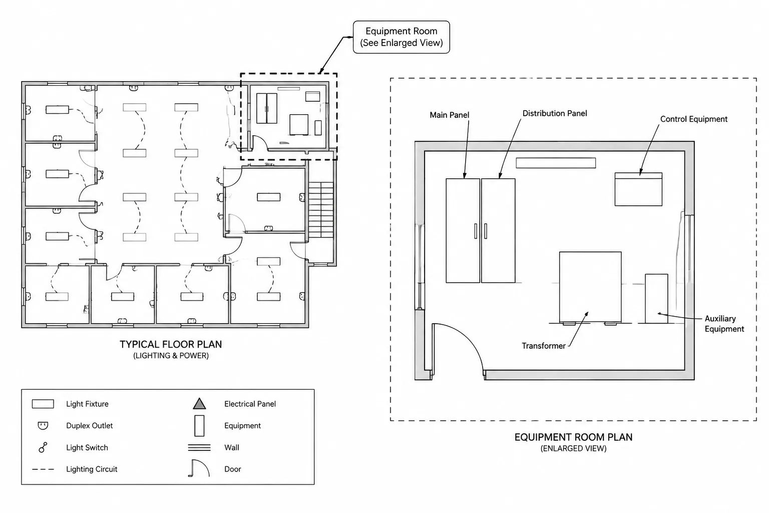
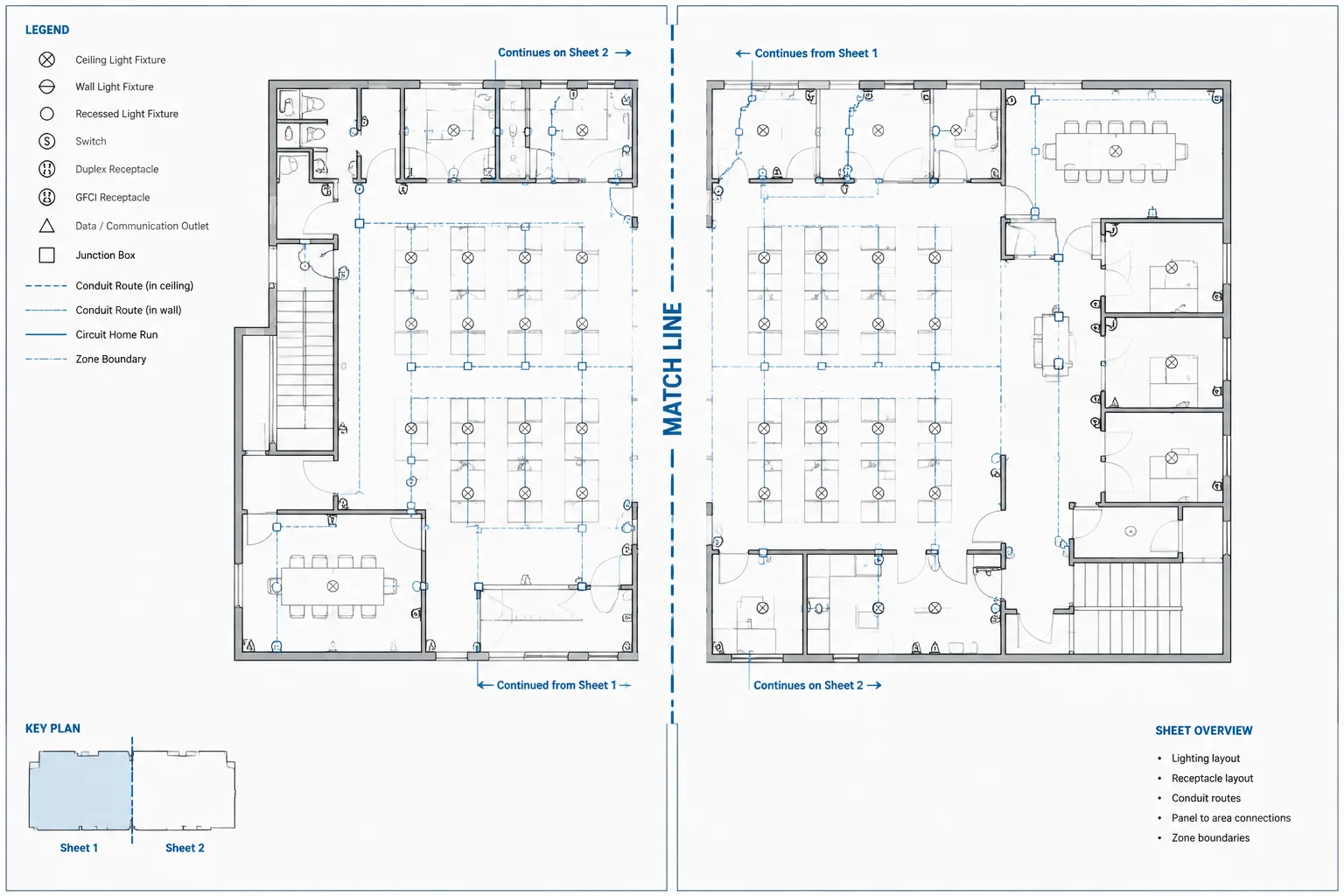
- Power plans: as part of a note, keyed symbol, or equipment connection annotation.
- Equipment details: to show the intended grounding relationship at an enclosure or assembly.
- Legends: to define the graphic and distinguish it from other grounding or conductor symbols.
Grounding terms that should not be confused
An equipment grounding conductor is not the same drafting concept as a grounded circuit conductor or a grounding electrode conductor. These terms describe different functions and should not share a symbol unless the drawing legend clearly establishes the intended meaning. Consistent labels help prevent ambiguity during coordination and review.
CAD placement and documentation checklist
- Open the DWG in a controlled file before inserting it into a project drawing.
- Inspect the block name, base point, entities, attributes, and layer properties.
- Match lineweight, color, linetype, and text style to the project CAD standard.
- Confirm that the symbol remains readable at the intended plotted scale.
- Use an annotation or legend entry when the graphic could have more than one interpretation.
- Check that conductor lines and leaders connect cleanly without gaps or misleading overlaps.
- Coordinate the symbol with panel, equipment, feeder, grounding, and general-note documentation.
- Plot or publish a test sheet to verify visibility in the final deliverable.
Related drawing-reference topics
This block is most useful when coordinated with electrical grounding symbols, single-line diagram symbols, panel and distribution graphics, conductor annotations, equipment connection details, CAD layer conventions, and electrical legends. Reviewing these related topics together creates a clearer documentation system than placing an isolated symbol without context.
Professional review remains important
A downloaded CAD block should be treated as editable reference content. The designer or responsible reviewer should verify that its meaning, placement, and annotation agree with the project documents. Field installation, conductor selection, and electrical safety decisions require qualified professional evaluation and are not established by the DWG graphic alone.

Frequently asked questions
What is an equipment grounding conductor DWG block?
It is a reusable CAD graphic intended to help identify an equipment grounding conductor or grounding connection in electrical documentation. The exact appearance and application depend on the drawing legend and drafting convention.
Can the block be used in a single-line diagram?
It may be used when its graphic meaning matches the project legend and the diagram’s documentation method. Some single-line diagrams communicate grounding through notes or connection lines instead of a standalone symbol.
Is an equipment grounding conductor the same as a grounded conductor?
No. They represent different electrical functions. Drawings should use clear symbols, line conventions, and labels so readers do not confuse them.

Should the downloaded block remain on its original layer?
Not automatically. Inspect the source layer and move or remap the block according to the project’s approved CAD layer standard. Avoid changing geometry or attributes without checking how the symbol is defined in the legend.
Does placing the symbol make a drawing code compliant?
No. A symbol only communicates design information. Compliance depends on the complete design, conductor documentation, equipment relationships, applicable requirements, and professional review.
What should be checked before plotting?
Verify symbol readability, lineweight, text visibility, connection points, leader placement, and consistency with the legend. Also check that nearby graphics do not conceal or alter the apparent grounding connection.










Leave a Reply
You must be logged in to post a comment.