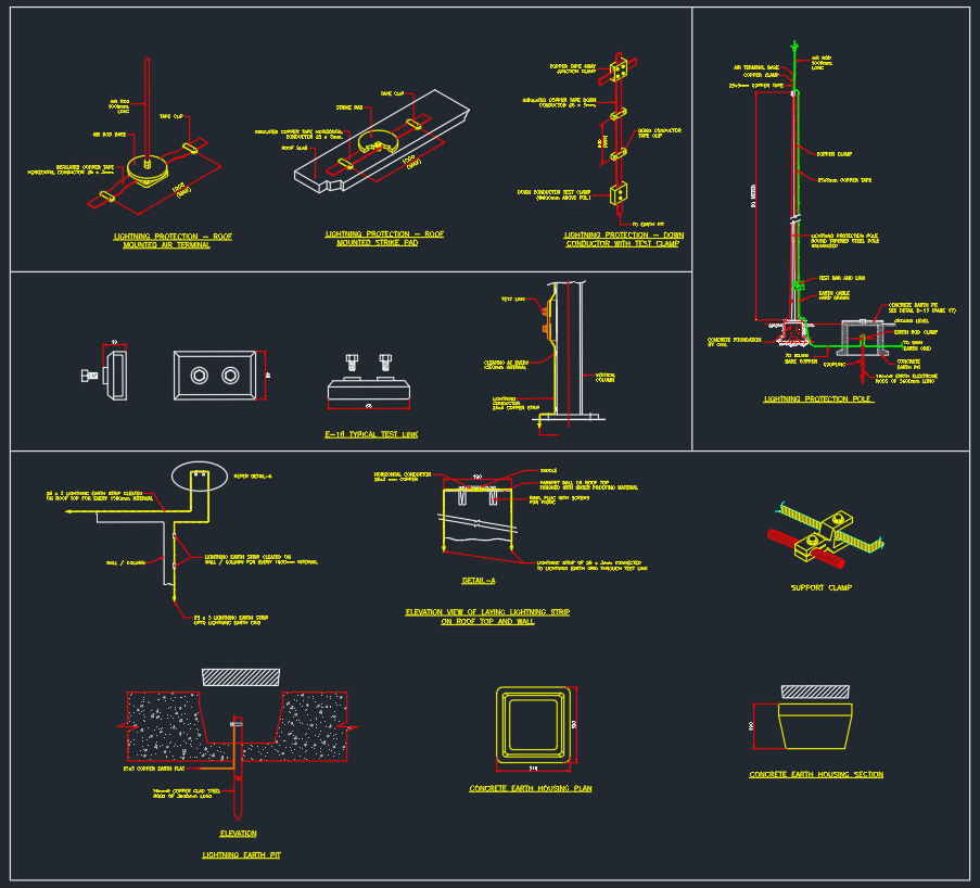
This lightning protection system DWG provides drawing content for documenting rooftop strike-termination components and the associated earth pit reference. It can support roof plans, grounding details, electrical legends, and coordinated building-services drawings.
Before incorporating the blocks into a project, review their linework, labels, units, scale, layers, and intended drawing context. Lightning protection design depends on the building, site conditions, applicable requirements, and coordination with other disciplines, so a CAD block should be treated as a drafting resource rather than a complete engineered design.
Download a high-quality DWG file featuring a complete **Lightning Protection System** including **LIGHTNING EARTH PIT**, **ROOF MOUNTED STRIKE**, and **ROOF MOUNTED AIR TERMINAL** CAD blocks. This detailed AutoCAD drawing is perfect for architects, engineers, and designers working on building safety and electrical grounding solutions. The file showcases precise layouts for rooftop lightning protection, earth pit installation, and air terminal placements, ensuring effective lightning risk management. Fully compatible with AutoCAD and other CAD software, this DWG file streamlines your design process and meets industry standards for lightning protection systems. Ideal for commercial, industrial, and residential projects.
Please log in or register to download this file.
What the lightning protection CAD content represents
The drawing includes components labeled LIGHTNING EARTH PIT, ROOF MOUNTED STRIKE, and ROOF MOUNTED AIR TERMINAL. Together, these labels address two important documentation areas: rooftop strike-termination equipment and the connection to an earth-termination or grounding arrangement.

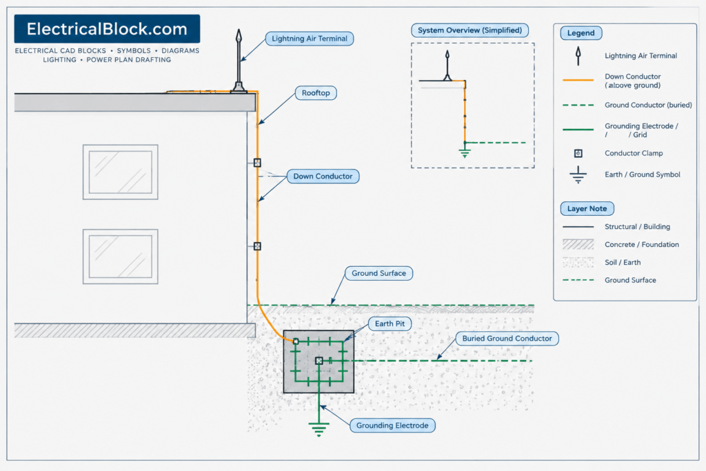
An air terminal is shown on drawings to identify a designated strike-termination point at the roof. The earth pit detail commonly represents an accessible location associated with the grounding or earth-termination system. Exact construction, conductor routing, bonding, inspection access, and grounding arrangements must be established from the approved project design.
How to use the blocks in an electrical drawing set
- Roof plans: Place symbols only after coordinating roof edges, elevations, equipment, drainage features, access routes, and architectural elements.
- Grounding details: Use the earth pit block with clear references to the applicable grounding layout, detail, or project note.
- Legends: Match block names and graphical symbols to the terminology used throughout the drawing set.
- Sections and elevations: Add detail references where a plan symbol alone does not explain mounting or routing.
- Layer control: Assign the imported geometry to project-approved layers so lineweight, color, plotting, and visibility remain consistent.
Important drafting checks
Confirm the insertion units and intended plotted scale before placing the DWG content. Inspect for duplicate geometry, unnecessary hatches, disconnected linework, text-style substitutions, and objects located far from the main drawing. These checks help prevent plotting problems and keep the project file manageable.
The phrase ROOF MOUNTED STRIKE may be project-specific terminology. Do not assume that it has the same meaning as an air terminal or another strike-termination component. Retain the source label when needed, but compare it with the project legend and rename copied instances only when the design authority has established the correct terminology.
Coordination with related electrical documentation
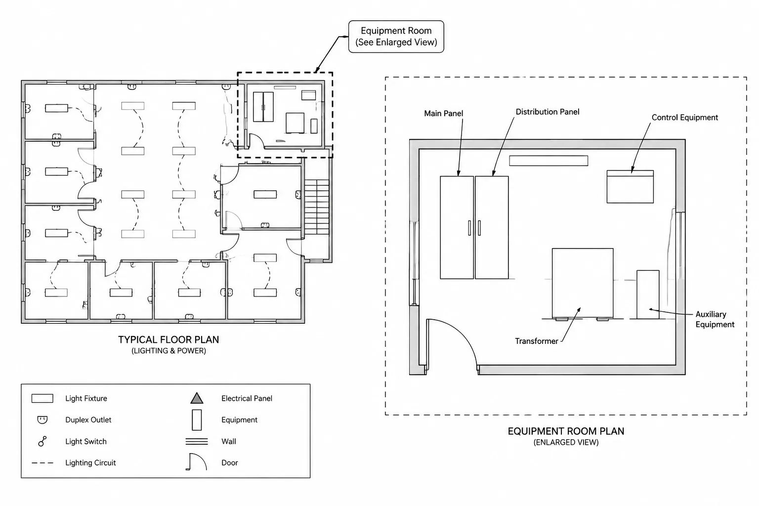
Lightning protection information is often coordinated with grounding drawings, roof equipment layouts, electrical site plans, conductor-routing details, equipment bonding notes, and drawing legends. Where the system interfaces with other electrical documentation, use consistent tags and cross-references so readers can follow the intended relationship without relying on the block graphic alone.
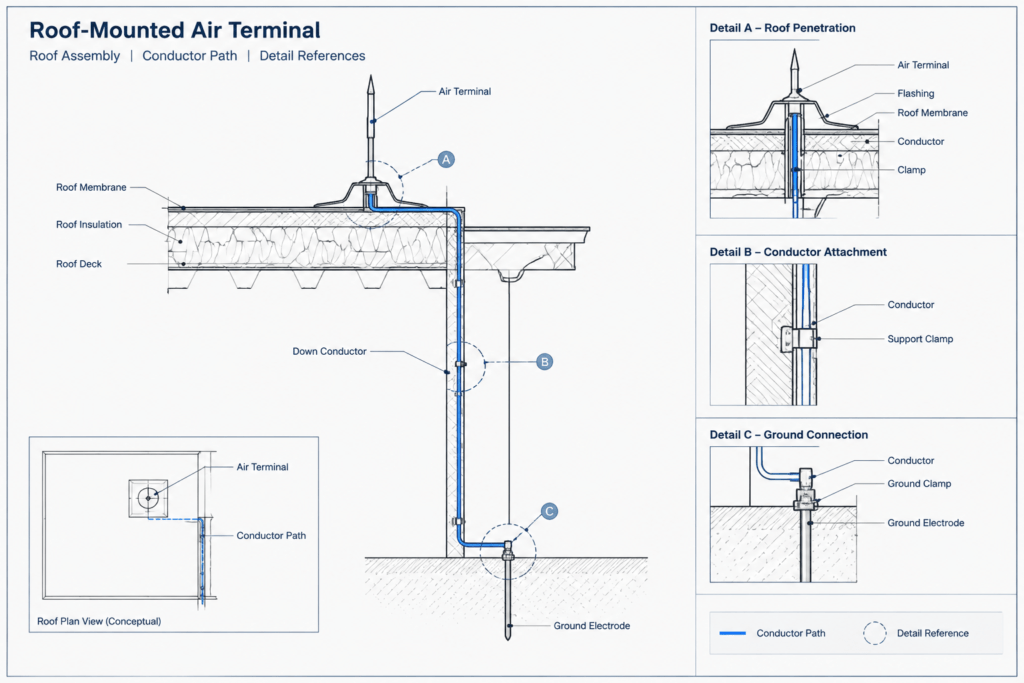
CAD geometry does not verify coverage, component selection, installation method, or compliance. Final locations and system details should be reviewed by the responsible qualified professional against project requirements and applicable regulations.
Frequently asked questions
What is included in this lightning protection system DWG?
The source content identifies a lightning earth pit, a roof-mounted strike component, and a roof-mounted air terminal. Review the downloaded drawing directly to confirm its geometry, annotations, layers, units, and detail organization.
Can the blocks be placed directly into a roof plan?
They can be used as drafting references, but placement should follow an approved lightning protection design. Coordinate the symbols with roof geometry, equipment, access areas, architectural features, and related grounding documentation.
Is an earth pit the same as the complete grounding system?
No. An earth pit symbol or detail generally identifies one accessible part of the earth-termination arrangement. The complete documentation may also need conductor routing, connections, bonding information, references, and project notes.
Should the original CAD layers be retained?
Inspect them before deciding. Source layers may be useful for understanding the block, while a project CAD standard may require approved layer names, colors, linetypes, and plotting behavior. Avoid moving all geometry to a single layer without first checking how the block is organized.
Does the DWG establish code compliance?
No. A CAD file supplies graphical content and labels; it does not establish that a proposed system meets project or regulatory requirements. Compliance and technical suitability require review by the responsible qualified professional.










Leave a Reply
You must be logged in to post a comment.