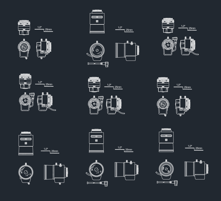
A bullet security cameras CAD block helps drafters represent camera locations consistently on security, electrical, and low-voltage drawings. The block can be placed wherever a camera must be identified, then coordinated with mounting surfaces, room geometry, exterior areas, and related plan annotations.
The downloadable DWG resource remains below. Before incorporating it into a drawing set, inspect the block definition, insertion point, units, linework, and layer behavior so they match the conventions of the destination file.
Discover a high-quality DWG file featuring a detailed CAD Block of Bullet Security Cameras, perfect for your security system design projects. This downloadable file is expertly crafted for architects, engineers, and designers who require precise security camera layouts in their CAD drawings. Ideal for both residential and commercial building plans, this Bullet Security Cameras CAD Block can be seamlessly integrated into your AutoCAD projects for enhanced visualization and planning. Ensure your next security installation is accurately represented with this easy-to-use, compatible DWG file. Optimize your workflow with this essential CAD resource today.
Please log in or register to download this file.
Using the Camera Block in a Drawing
Insert the block into a working copy of the plan and confirm that its apparent size is appropriate for the drawing. Position it at the intended mounting location and rotate it to communicate the viewing direction. If the project uses identifiers, assign a clear camera tag and coordinate that tag with the security device schedule, legend, or system diagram.

A camera symbol normally documents location and orientation rather than proving surveillance performance. Field of view, obstructions, lighting conditions, mounting requirements, cabling, and equipment selection require separate project review. Avoid treating the graphic alone as confirmation that an area has adequate coverage.
CAD Layer and Annotation Workflow
- Layer assignment: Place camera graphics on the project layer used for security or low-voltage devices rather than leaving them on an imported layer without review.
- Orientation: Rotate each instance deliberately so the plan communicates the intended viewing direction.
- Identification: Use concise tags that correspond with the project legend, schedule, or device list.
- Graphic clarity: Check lineweight, color, linetype, and plotted visibility against nearby architectural backgrounds.
- Block management: Use a consistent block name and avoid creating unnecessary duplicate definitions during repeated insertion.
- Coordination: Review camera locations alongside ceilings, doors, walls, equipment, cable routes, and other building systems.
Camera Symbol and Coverage Graphics
The device block and the coverage graphic serve different documentation purposes. The device symbol marks the camera location, while a directional line or field-of-view shape can communicate design intent. Keeping these elements separate may make revisions easier and allows coverage graphics to be shown only on drawings where they improve coordination.
When coverage shapes are included, present them as planning graphics rather than guaranteed performance boundaries. Final coverage depends on the selected equipment, installation conditions, site geometry, and professional design review.

Related Drawing References
This resource fits naturally with security camera symbols, low-voltage plans, equipment schedules, cable and conduit drafting, CAD layer standards, and drawing legends. These related references help connect a single device block to the broader documentation workflow without overcrowding the plan.
Pre-Issue Review Checklist
- Confirm the block uses the intended drawing units and scale conventions.
- Check the insertion point and rotation of every placed instance.
- Verify that tags agree with schedules and system diagrams.
- Look for conflicts with doors, ceilings, fixtures, equipment, and structural elements.
- Test visibility in the plotted sheet, not only in the CAD model space.
- Have camera locations and coverage intent reviewed by the responsible project professional.
Frequently Asked Questions
What does a bullet camera CAD block represent?
It is a reusable drawing object used to identify a bullet-style security camera on a CAD plan. Depending on the drawing convention, its orientation may also indicate the intended viewing direction.
Should the block be placed on an electrical layer?
Use the layer structure established for the project. Security cameras may be organized under security, communications, low-voltage, or another discipline-specific layer system. Consistency with the drawing legend and deliverable requirements is more important than a universal layer name.

Can the block confirm the camera field of view?
No. A symbol can communicate approximate design intent, but it does not confirm actual coverage. Equipment characteristics, mounting conditions, obstructions, lighting, and site geometry must be evaluated separately.
Should camera tags be part of the block?
They may be included as attributes or maintained as separate annotations. Attributes support consistent identification, while separate text can offer more placement flexibility. Use the method that aligns with the project schedule and CAD standards.
What should be checked after importing the DWG block?
Review units, apparent size, insertion point, layers, linework, block naming, rotation, and plotted appearance. Also check for duplicate definitions or unwanted imported layers before using the block throughout a project.












Leave a Reply
You must be logged in to post a comment.