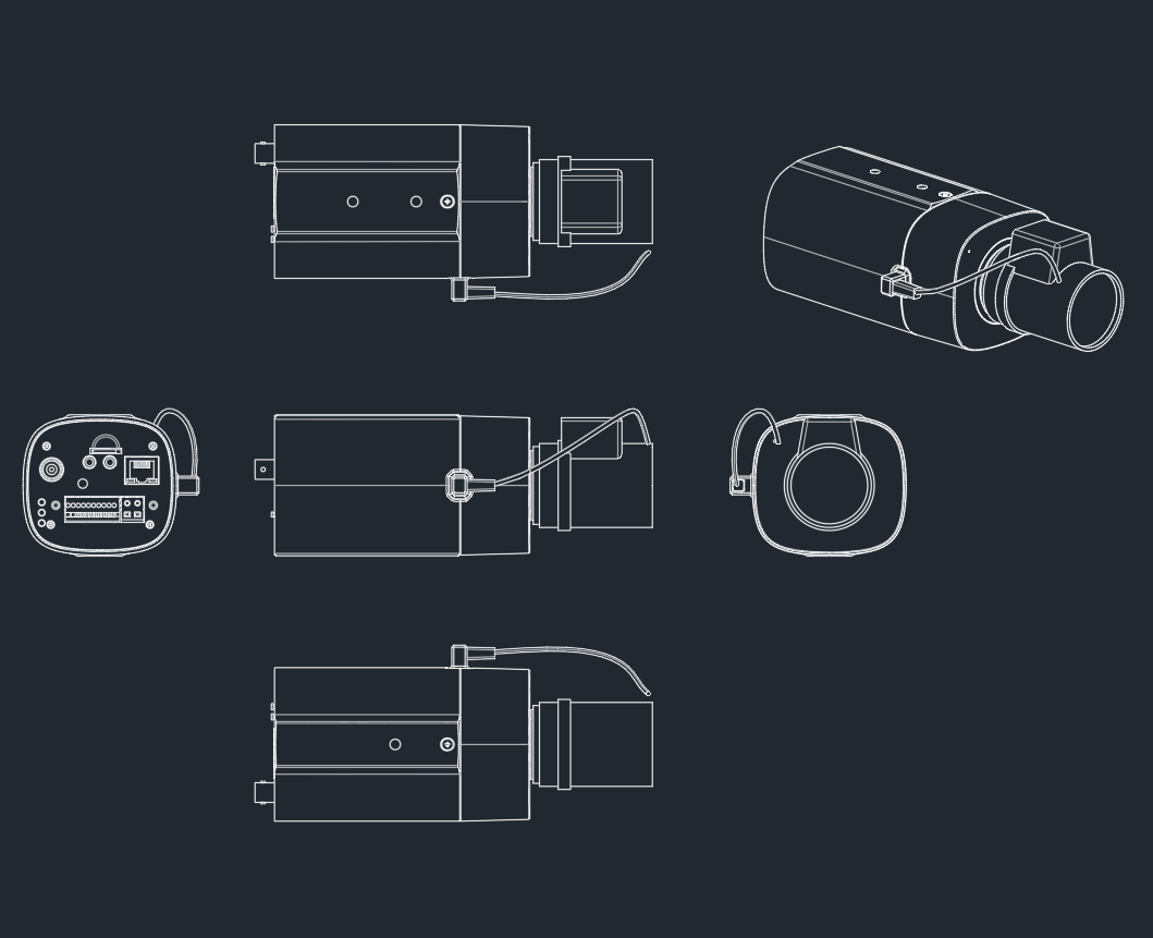
This day night box CCTV cameras CAD block provides multiple equipment views for security-system drawings and equipment-layout documentation. The front, side, and top representations can help drafters show the camera consistently across plans, elevations, schedules, and coordination details.
Use the block as a drafting resource rather than as a substitute for manufacturer data. Before placing it in a project drawing, confirm the file units, drawing scale, equipment orientation, mounting arrangement, and required clearances against the selected camera and its supporting hardware.
Download a high-quality DWG file of Day Night Box CCTV Cameras CAD Block, perfect for architects and engineers seeking precise security system layouts. This CAD Block showcases detailed front, side, and top views of Day Night Box CCTV Cameras, ensuring accurate representation in your AutoCAD projects. Ideal for designing surveillance systems in residential, commercial, and industrial buildings, this DWG file allows seamless integration and customization within your security plans. Fully compatible with AutoCAD and other leading CAD software, it streamlines your workflow and enhances your project’s professionalism.
Please log in or register to download this file.
Using the CCTV Camera Block in a Drawing Set
Select the view that matches the purpose of the drawing. A top view can support plan coordination, while front and side views can help communicate appearance, orientation, and spatial relationships in elevations or equipment details. Keep the chosen view aligned with the drawing’s established projection and annotation conventions.

Recommended CAD Checks
- Inspect units and scale: Compare the imported geometry with known project elements before relying on its displayed size.
- Review the insertion point: A logical base point makes placement, rotation, and replacement easier.
- Organize layers: Place camera geometry, labels, coverage graphics, and mounting information on appropriate project layers.
- Check linework: Remove accidental duplicates and confirm that lineweights remain legible at the intended plotting scale.
- Preserve orientation: Rotate the block deliberately so the camera direction is clear and consistent with nearby notes.
Camera Outline Versus Surveillance Symbol
An equipment outline and a plan symbol serve different documentation purposes. The outline communicates the camera’s physical form, while a simplified CCTV symbol often identifies location and viewing direction more clearly on a crowded plan. A coordinated drawing set may use the detailed block in equipment views and a simpler symbol in the surveillance layout.
Coverage cones, identification tags, cable references, mounting notes, and device schedules should remain separate from the equipment geometry when practical. This approach improves layer control and allows project-specific information to be revised without editing the underlying camera block.
Coordination and Verification
The label “day night box camera” identifies a general equipment category; it does not establish lens characteristics, image performance, enclosure suitability, mounting method, power requirements, or network requirements. Verify those items from approved project documentation and current manufacturer information.
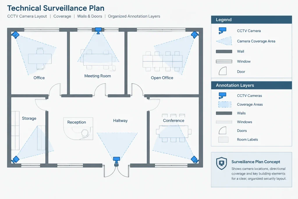
For clearer drawing coordination, relate this resource to CCTV symbols, security-system legends, equipment schedules, cable and conduit drafting, low-voltage plan annotations, and CAD layer-management references. Final placement should also be reviewed against architectural elements, lighting conditions, access needs, and other building systems.
Frequently Asked Questions
Which views are included in this CCTV camera CAD block?
The source content identifies front, side, and top views. These views can be selected according to whether the drawing is a plan, elevation, equipment detail, or coordination sheet.
Should the detailed camera block be used as the plan symbol?
Not necessarily. Detailed outlines can be useful in equipment drawings, but a simplified CCTV symbol may remain clearer on a busy security plan. Follow the project legend and drawing conventions.

What should be checked after importing the DWG?
Confirm units, apparent scale, insertion point, layer assignment, orientation, linework quality, and plotted readability. Compare the geometry with approved equipment information before using it for coordination.
Does the block define the camera’s field of view?
The equipment views alone should not be treated as verified coverage information. Viewing direction and coverage graphics depend on the selected camera, lens, mounting position, and project requirements.
Can the block be edited for a project drawing?
DWG geometry can generally be incorporated into a project CAD workflow, but edits should follow office standards. Keep project annotations and coverage graphics separate where practical so the original equipment representation remains manageable.










Leave a Reply
You must be logged in to post a comment.