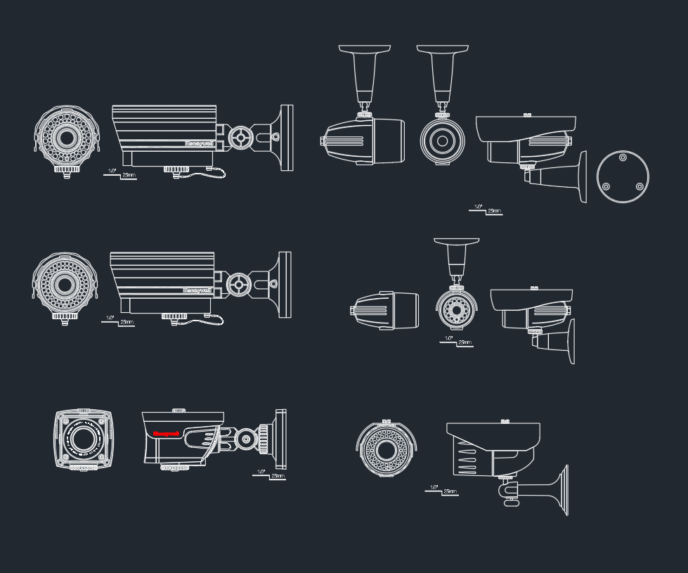
Outdoor Security Cameras DWG Blocks help organize surveillance equipment within architectural plans, security layouts, and facility documentation. This reference page provides the downloadable CAD resource described in the source content, along with practical guidance for using camera blocks clearly in project drawings.
Use the block as part of a coordinated drawing workflow with equipment layouts, electrical legends, lighting plans, and other security documentation. The camera symbol should communicate the intended equipment location and drawing context without replacing the project’s approved design information.
Download our detailed **Outdoor Security Cameras DWG file** for your architectural and security system projects. This high-quality CAD Block provides accurate representations of outdoor surveillance cameras, ideal for use in security layout planning, building blueprints, and facility design. The file is fully compatible with AutoCAD and other leading CAD software, ensuring seamless integration into your drawings. Perfect for architects, engineers, and security professionals, this DWG file allows you to easily visualize and position outdoor security cameras in both residential and commercial project plans, enhancing safety and situational awareness.
Please log in or register to download this file.
How to use outdoor security camera blocks in CAD drawings
Outdoor surveillance camera blocks are useful for showing equipment locations on site plans, floor plans, building elevations, and security system layouts. Their main value is visual coordination: designers can identify where cameras are represented and review their relationship to entrances, circulation areas, exterior walls, parking areas, and other documented spaces.
Coordinate the block with the drawing set
Before placing a camera symbol, review the drawing type, scale, orientation, layer organization, and project legend. A plan-view symbol may communicate location and direction differently from an elevation or detail view. Keep the block aligned with the drawing’s established graphic language so it remains easy to read when combined with architectural, electrical, and security information.
- Security layouts: Use camera blocks to distinguish surveillance equipment from general architectural features.
- Equipment plans: Coordinate camera locations with other site and building equipment shown in the drawing.
- Electrical documentation: Refer to the project’s electrical legends and power documentation when equipment connections must be coordinated.
- Drawing organization: Maintain clear layers, labels, and annotations so the block does not obscure important plan information.
What to verify before issuing a drawing
Confirm that the selected block represents the intended camera type or visual convention used by the project team. Check orientation, visibility, layer assignment, annotation consistency, and coordination with architectural backgrounds. The CAD block is a drafting aid; final equipment selection, coverage, mounting, wiring, networking, and power requirements must be established by the responsible design team.
Related CAD reference topics
This resource fits naturally with electrical legends, equipment layouts, lighting and power plan drafting, cable and conduit documentation, and security system drawing organization. Reviewing those related drawing concepts can help keep surveillance symbols consistent across a complete set of plans.
Frequently asked questions
What is included in the outdoor security cameras DWG resource?
The source content identifies the download as a detailed DWG file containing representations of outdoor surveillance cameras for architectural and security system projects.
Can the camera blocks be used in AutoCAD drawings?
Yes. The source description states that the DWG file is compatible with AutoCAD and other leading CAD software.
Where can outdoor camera blocks be placed?
They can be used in appropriate security layouts, building plans, blueprints, facility design drawings, and equipment documentation, provided the placement follows the project’s drafting standards.
Do these blocks determine camera coverage or final installation requirements?
No. A CAD block communicates drawing intent and equipment representation. Coverage, mounting, connectivity, power, and final installation requirements require project-specific review by qualified design professionals.
Should camera symbols be coordinated with electrical drawings?
Yes. When a project includes power, communication, or conduit documentation, coordinate the camera representation with the applicable electrical plans, legends, and equipment information.












Leave a Reply
You must be logged in to post a comment.