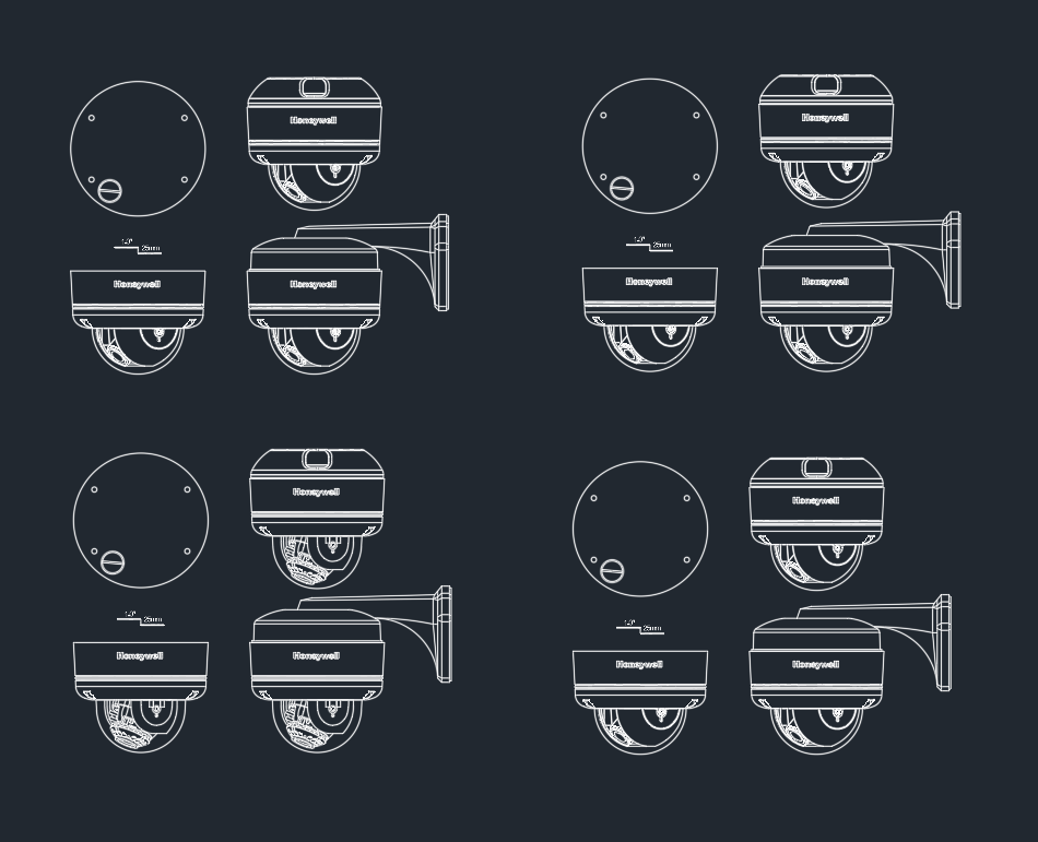
An outdoor PTZ camera DWG block can help organize surveillance equipment in architectural, security, and electrical drawing workflows. PTZ refers to pan, tilt, and zoom functions, while the CAD block provides a reusable graphical representation for plan development and coordination.
Use the source file as a drafting aid when placing camera symbols, reviewing equipment relationships, and communicating surveillance intent. The block should be coordinated with the project drawing standards, layer naming, orientation, and documentation requirements before publication.
Download our high-quality Outdoor PTZ Camera DWG file, designed as a detailed CAD Block for your architectural and security system projects. This versatile DWG file showcases an Outdoor PTZ Camera with precise dimensions and realistic detailing, making it ideal for integration into security layouts, surveillance plans, and building designs. Fully compatible with AutoCAD and other major CAD software, the Outdoor PTZ Camera CAD Block streamlines your workflow, ensuring easy insertion and editing. Perfect for architects, engineers, and security professionals, this file supports accurate planning and visualization for both residential and commercial projects. Enhance your next AutoCAD design with this essential security camera CAD resource.
Please log in or register to download this file.
How to use an outdoor PTZ camera CAD block
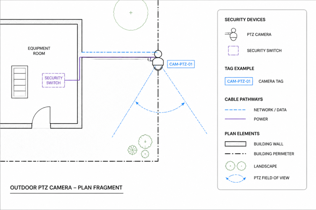
A camera block is most useful when it is treated as part of a larger drawing language rather than as an isolated graphic. In a plan view, it can identify the approximate equipment location and support discussions about coverage, access, mounting context, cable routing, and nearby building elements. In security layouts, the graphic may be paired with camera tags, device schedules, notes, and a legend that explains the project’s symbols.
Coordinate the block with drawing conventions
- Layer organization: Place the camera graphic on the project’s designated security, low-voltage, or equipment layer rather than assuming the downloaded layer structure matches the project standard.
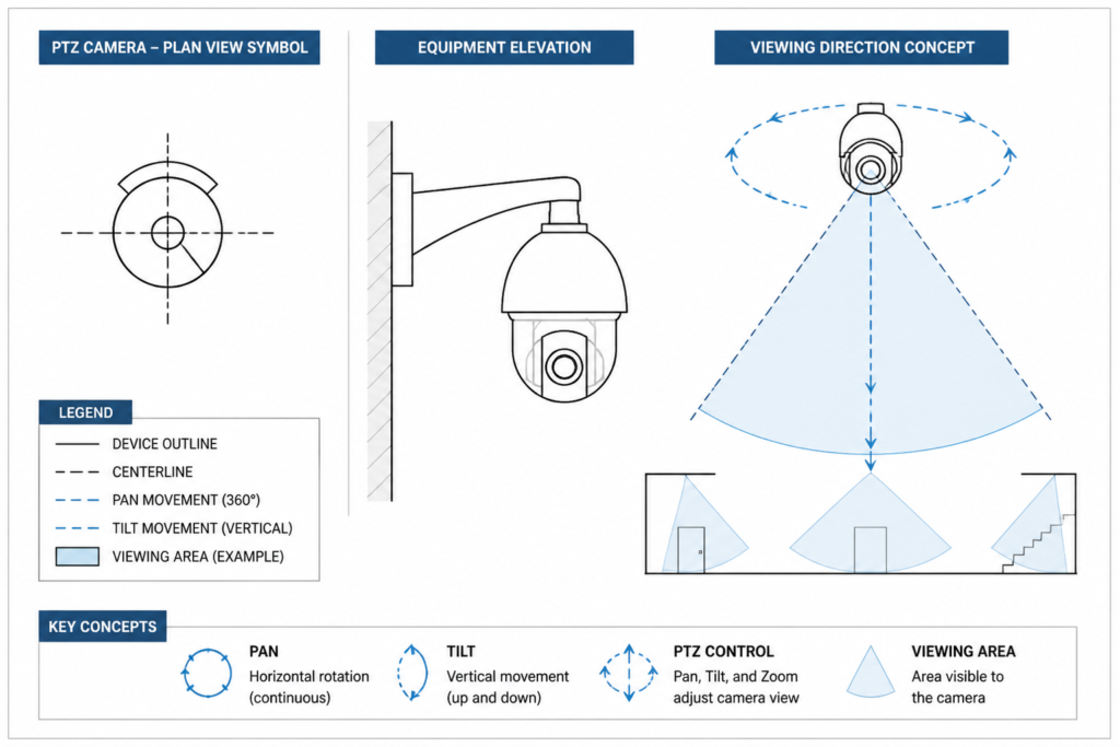
- Orientation: Align the block with the intended viewing direction or use a separate coverage graphic when the drawing needs to communicate an observation area.
- Scale and insertion: Check units, insertion behavior, lineweight, and displayed scale after importing the block into the host drawing.
- Legends and tags: Pair the symbol with a clear device identifier and legend entry so readers can distinguish PTZ equipment from fixed cameras and other security devices.
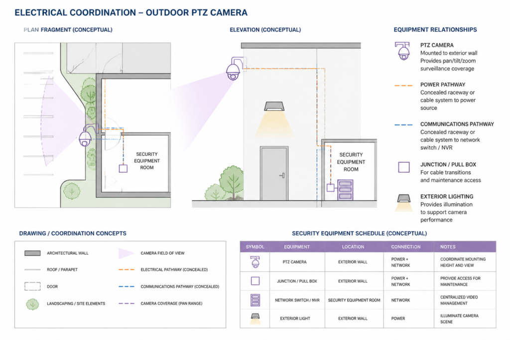
- Coordination: Compare the proposed location with architectural backgrounds, lighting, access-control equipment, power sources, communications pathways, and maintenance access.
What the DWG block does—and does not—show
The block supports visual documentation and coordination, but a graphic alone does not establish the final field location, viewing performance, mounting method, power arrangement, network design, weather protection, or protective-device requirements. Those items require project-specific information and review by the responsible design and installation professionals.
Useful drawing relationships
For a complete surveillance drawing, consider how the PTZ symbol relates to camera schedules, equipment elevations, single-line or riser diagrams, conduit and cable plans, panel documentation, and security system notes. Keeping the symbol consistent across these views reduces ambiguity when a project moves from concept documentation to coordinated design.
Quick reference
- Primary purpose: Identify an outdoor PTZ camera graphically in a CAD drawing.
- Typical views: Plan layouts, security plans, equipment coordination drawings, and conceptual building documentation.
- Related documentation: Legends, device tags, camera schedules, cable pathways, equipment elevations, and coordination notes.
- Review priority: Units, layer standards, orientation, scale behavior, and consistency with the project symbol library.
Frequently asked questions
What is an outdoor PTZ camera DWG block?
It is a reusable CAD graphic representing an outdoor pan-tilt-zoom camera for use in architectural, security, and coordination drawings.
Can this block be used in a security plan?
Yes, the source file is intended to support security layouts and related building drawings. Confirm its units, layers, orientation, and graphic conventions in the project file before using it in published documentation.
Does the block show the camera’s actual coverage area?
Not by itself. A camera symbol identifies equipment graphically, while coverage studies require project-specific placement, viewing objectives, obstructions, and system information.
Is the DWG block an installation-ready design?
No. It is a drafting and visualization resource, not a substitute for coordinated design, equipment selection, field verification, or professional review.
What should be coordinated around a PTZ camera?
Review the camera location against architectural surfaces, mounting conditions, lighting, access and maintenance needs, power and communications pathways, and related security equipment.










Leave a Reply
You must be logged in to post a comment.