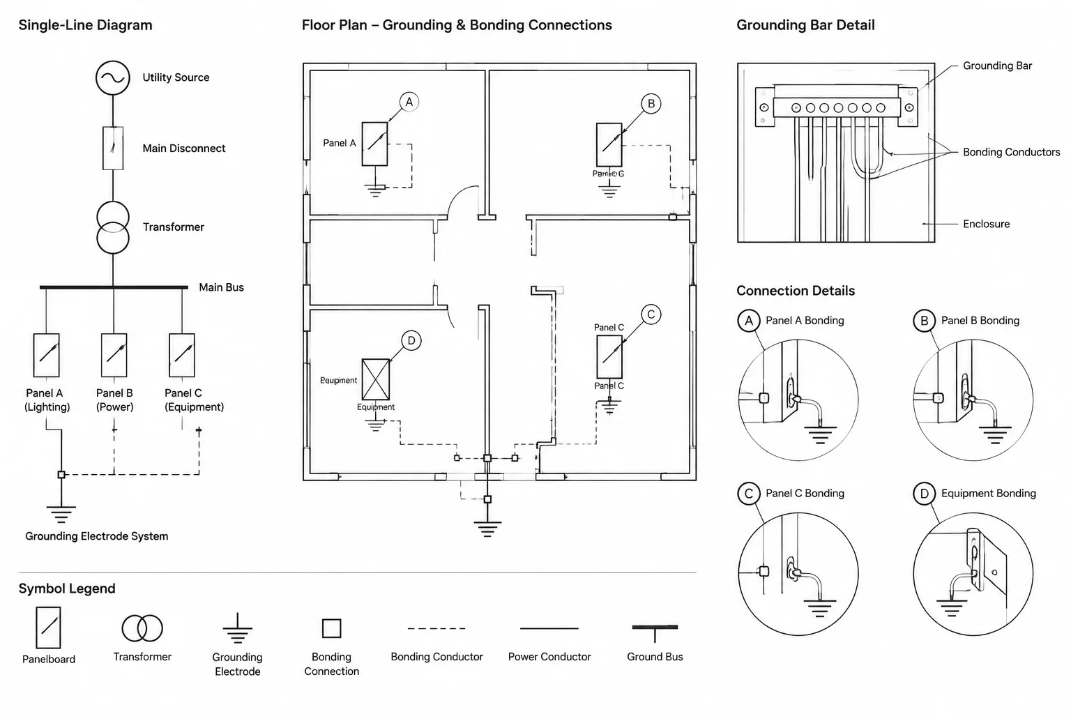
Grounding and bonding drawings in CAD must connect system intent with physical locations and construction interfaces. This reference explains how to divide that information among single-line diagrams, plans, layouts, sections, details, and schedules without creating conflicting documentation.
Use the workflow as a drafting and quality-control framework rather than a substitute for project engineering. The applicable connections, materials, terminology, and installation requirements must come from the approved design and governing project criteria.
Grounding and bonding information rarely belongs on only one electrical drawing. A single-line diagram may communicate the overall system relationship, while floor plans locate connection points and details explain how conductors, electrodes, enclosures, and building systems relate. If these views are drafted independently, the result can be duplicated notes, conflicting tags, or connections that appear in one view but disappear in another.
A reliable CAD workflow treats grounding and bonding as a coordinated documentation system. The objective is not to fill every sheet with the same technical notes. It is to assign each drawing type a clear purpose, establish consistent identifiers, and make the path from diagram to physical location easy to follow.
Grounding and bonding are related but not interchangeable
Drawing language should preserve the distinction between grounding and bonding. Grounding documentation commonly addresses the relationship between an electrical system and an electrode or earth reference. Bonding documentation shows intentional electrical continuity among conductive parts, equipment enclosures, raceways, structural elements, or other designated systems.
The exact arrangement depends on the electrical system, project conditions, governing requirements, and engineering decisions. CAD blocks and typical details should therefore be treated as graphic starting points rather than proof that a particular connection is correct for a project.
Consistent terminology matters because vague labels such as “ground wire” can describe several different functions. Where the design requires a more specific distinction, use the project’s defined terms for conductors, bonding jumpers, grounding electrode connections, equipment grounding paths, and related components.
Assign information to the right drawing type
Each view should answer a different documentation question. Trying to show every connection on every sheet creates clutter and increases the number of places that must be revised.
| Drawing type | Primary purpose | Typical grounding and bonding content |
|---|---|---|
| Single-line diagram | Explain system relationships | Sources, distribution equipment, major bonding points, grounding electrode relationships, and references to supporting details |
| Floor or site plan | Show physical location and routing intent | Electrode locations, grounding bars, equipment connection points, exposed routing where relevant, and detail callouts |
| Equipment layout | Coordinate space and interfaces | Ground bars, connection zones, adjacent metallic systems, and access considerations requiring coordination |
| Section or elevation | Clarify vertical and spatial relationships | Connections at equipment, structural elements, rooms, roofs, below-grade areas, or changes in elevation |
| Grounding detail | Explain a specific assembly | Connection sequence, component relationships, material interfaces, labels, and references to plans or diagrams |
| Schedule or connection list | Organize repeated data | Identifiers, origins, destinations, conductor descriptions, connection types, and associated drawing references |
Begin with a connection map
Before drafting individual details, create a simple connection map of the grounding and bonding scope. This may be a controlled sketch, a diagram worksheet, or a marked-up one-line. Its purpose is to identify the major nodes and determine where each relationship will be documented.
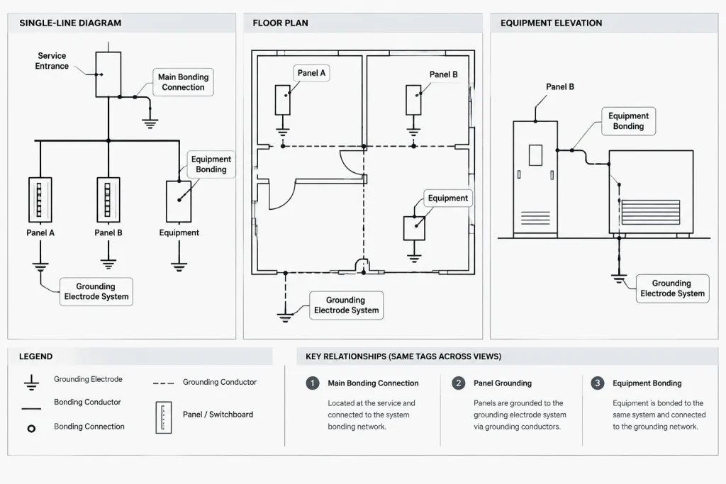
Potential nodes may include service or source equipment, separately derived systems, distribution equipment, grounding bars, grounding electrodes, structural elements, telecommunications grounding interfaces, lightning protection interfaces, generators, and large mechanical or process equipment. Not every project contains all of these elements, and their presence does not automatically define how they must be connected.
For each node, ask:
- Is it represented on the single-line diagram?
- Does its physical location need to appear on a plan?
- Is a section, elevation, or enlarged view needed to explain the connection?
- Does a repeated condition belong in a typical detail?
- Which discipline owns the equipment or system being referenced?
- Which drawing is the controlling source if information differs?
Build a clear graphic hierarchy
Grounding diagrams can become difficult to read when connection lines compete with feeders, equipment outlines, and annotation. Use a deliberate hierarchy so the reader can distinguish system topology from physical routing.
Separate conceptual and physical linework
A line on a single-line diagram usually communicates an electrical relationship, not a measured route. A line on a plan may indicate routing intent, an exposed conductor path, or simply a connection between a tag and a symbol. The legend or drawing notes should make that meaning clear.
Avoid using one line type for several unrelated purposes. If diagrammatic connections, concealed paths, below-grade routes, and continuation lines require different interpretations, establish distinct conventions that remain legible in both color and monochrome output.
Keep symbols simple
Use compact symbols for electrodes, grounding bars, connection points, and bonds, then place detailed assembly information in referenced details. Overly literal symbols become unreadable at plan scale and often fail when drawings are reduced.
Symbols should have stable insertion points and predictable rotation behavior. If a block contains attributes, reserve them for information that benefits from structured editing or extraction, such as an identifier or connection reference. Do not bury essential instructions inside attributes that may be invisible in some view states.
Use junction graphics deliberately
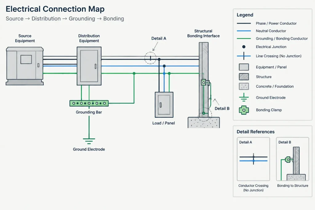
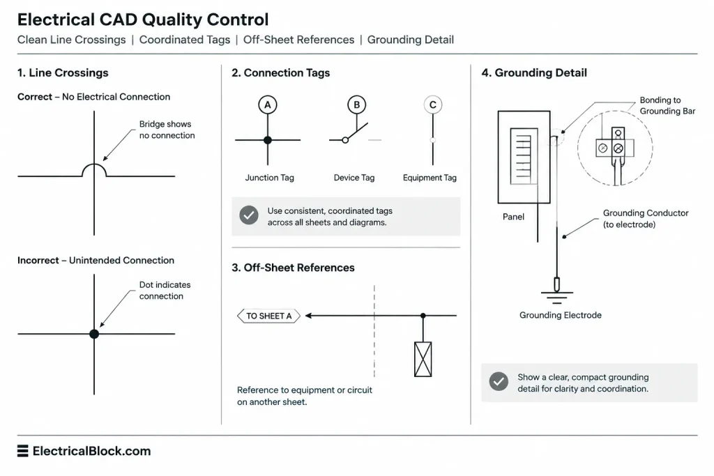
Where lines meet on a diagram, make intentional connections visually different from crossings. Junction markers, offsets, or other office-approved conventions can prevent a reader from interpreting an unconnected crossing as a bond. Review the plotted sheet rather than relying only on the CAD display.
Create a coordinated tagging system
Tags help connect diagrammatic information to physical views. A grounding bar shown on a room plan, for example, should use the same identifier when it appears in an elevation, detail, or connection list.
A practical identifier system should be unique, readable, and stable through revisions. It should not depend entirely on sheet position because details and viewports may move. If identifiers encode location or equipment type, document the format so future editors do not create competing patterns.
Useful tag categories may include:
- Grounding or bonding connection points
- Ground bars or bus assemblies
- Grounding electrodes or electrode groups
- Connections to structural or building systems
- Diagram continuations and off-sheet references
- Typical detail references
A tag should lead to useful information. Avoid assigning identifiers that never appear in a schedule, detail, or related view.
Draft details around interfaces, not isolated objects
The most useful grounding details explain relationships between components. A drawing of a bar alone communicates little unless it also identifies the connected systems, mounting context, conductor destinations, and relevant references.
Organize a detail from general context to specific connection. Show enough surrounding geometry to establish orientation, but screen or simplify background elements that do not affect the electrical interface. Clearly distinguish diagrammatic geometry from project-specific construction geometry.
Typical details should also define their limits. A note such as “typical” should not imply that the condition applies everywhere without review. Use plan callouts or a connection list to identify where the detail applies, and provide exceptions when equipment or site conditions differ.
Coordinate with other disciplines
Grounding and bonding drawings often reference items designed or located by other disciplines. Structural steel, piping, communications infrastructure, lightning protection components, and mechanical equipment may all create coordination interfaces.
Use architectural and engineering backgrounds to confirm location, but avoid copying uncontrolled geometry into the electrical file as if it were authoritative. Identify ownership where necessary, and distinguish an electrical connection requirement from the design of another discipline’s system.
During coordination, check whether referenced objects have moved, changed identifiers, or been removed. A connection note pointing to an outdated equipment tag can remain graphically valid while becoming technically useless.
Apply a cross-drawing review
Before issue, review the documentation as a connected set rather than checking each sheet in isolation.
- Trace each major grounding or bonding relationship from the one-line to its supporting plan or detail.
- Confirm that equipment names and identifiers match across all views.
- Check that plan callouts point to existing details and correct sheets.
- Verify that connection symbols appear in the legend when their meaning is not self-evident.
- Look for lines that appear connected only because they cross.
- Search for duplicate tags, missing destinations, and orphaned schedule entries.
- Confirm that demolition, existing, new, and future conditions are visually distinguishable where applicable.
- Plot in the intended output style and inspect dense diagram areas at publication size.
Control reusable CAD content
A shared library can improve consistency, but grounding and bonding content deserves careful review because small graphic changes can alter meaning. Maintain separate library objects for symbols, diagram fragments, and full details. A symbol may be broadly reusable, while a complete detail is more likely to contain assumptions that require project-specific editing.
Store source information with the library record, including the block name, intended view type, revision status, and any limitations. When a typical detail is brought into a project, copy it into a controlled project location and document modifications rather than silently changing the office master.
The final drawing set should communicate a traceable design intent without pretending that a generic CAD object resolves every project condition. Clear division of information, consistent tags, deliberate linework, and cross-sheet review make grounding and bonding drawings easier to understand and safer to coordinate.
Turn the drawing set into a traceable record
A useful coordination test is whether a reviewer can start with a tagged connection on one drawing and locate its related equipment, detail, and documentation without guessing. Traceability depends on stable identifiers, accurate callouts, and a clearly defined controlling view.
When a connection changes, record the affected views before editing. A simple revision worksheet can identify the originating equipment, destination, associated tag, plan location, detail reference, schedule entry, and discipline interface. This makes it less likely that a correction will be completed on one sheet while obsolete information remains elsewhere.
Separate drafting status from design status
CAD geometry can look complete even when an interface is unresolved. Use the project’s approved notation method to distinguish confirmed connections from coordination items, background references, and pending decisions. Temporary status graphics should not be allowed to resemble final construction information.
Comments and markups should also identify the type of issue. A missing callout is a documentation problem, while an uncertain destination or system relationship requires design review. Keeping those categories separate helps direct questions to the appropriate team member.
Perform a final handoff check
- Identifiers: Confirm that each repeated tag retains the same meaning throughout the drawing set.
- References: Open each plan, diagram, detail, and schedule destination rather than checking callout text alone.
- Line meaning: Verify that crossings, junctions, continuations, and physical routes remain visually distinct after plotting.
- Backgrounds: Review referenced equipment, rooms, structural elements, and other discipline objects for movement or renaming.
- Exceptions: Confirm that project-specific conditions do not appear to be covered by an inapplicable typical detail.
- Deliverables: Check that required layers, attributes, external references, and plot conventions remain understandable to the receiving team.
This handoff review does not validate the electrical design itself. It confirms that the approved design intent is represented consistently and can be followed across the published documents.
Frequently asked questions
Should grounding and bonding information appear only on the single-line diagram?
No. The single-line diagram communicates system relationships, while plans, sections, layouts, and details can locate and explain physical interfaces. The information should be divided by drawing purpose and connected with consistent references.
What is the difference between a grounding symbol and a grounding detail?
A symbol is a compact graphic used to identify a connection, component, or relationship. A detail provides the surrounding context, component interfaces, notes, and references needed to explain a specific assembly.
How should a CAD team handle repeated connection points?
Assign stable identifiers and use them consistently in diagrams, plans, details, and connection lists. Repeated conditions may reference a typical detail, but each application still requires review against the actual project condition.
Can one CAD block represent every grounding or bonding condition?
No. A reusable block can standardize graphic language, but it cannot determine whether a connection is appropriate. Project-specific design decisions and interfaces must be reviewed before a symbol or detail is applied.
How can crossing lines be prevented from looking connected?
Use the office-approved convention for junctions, offsets, and line crossings, and verify the result in the intended plot style. The distinction should remain clear without relying only on screen color.
Who should control information shared with another discipline?
Ownership should follow the project’s coordination plan. Electrical drawings can identify the required interface, but geometry and design information belonging to another discipline should remain clearly attributed and verified against the current background.










Leave a Reply
You must be logged in to post a comment.