
A reliable electrical symbol legend in CAD connects the graphic language of the plans with the wider documentation set. It helps readers distinguish device identity from status, circuit references, schedule tags, pathway conventions, and other annotations that may look similar but serve different purposes.
The following guidance explains how to organize, coordinate, and review a project-specific drawing key without turning the legend into a duplicate schedule or an uncontrolled catalog of office symbols.
An electrical symbol legend is more than a collection of blocks placed in an empty corner of a sheet. It is the drawing key that helps readers interpret device symbols, line types, tags, abbreviations, and graphic conventions throughout the electrical set. When the legend is incomplete or disconnected from the plans, even well-drafted drawings can become difficult to understand.
A useful electrical symbol legend in CAD should reflect the actual project rather than every symbol available in a company library. It also needs to distinguish graphic meaning from technical requirements. The legend can identify what a symbol represents, but equipment ratings, installation requirements, circuit information, and product characteristics usually belong in schedules, notes, specifications, or associated diagrams.
What an Electrical Symbol Legend Should Accomplish
The primary purpose of a legend is interpretation. It gives reviewers, estimators, installers, owners, and other disciplines a common reference for reading the drawings. A strong legend should answer several basic questions:
- What device or drawing concept does each symbol represent?
- Does symbol orientation, fill, line style, or added notation change its meaning?
- Which tags connect the symbol to a schedule, circuit, detail, or diagram?
- Which conventions are project-specific rather than generally assumed?
- Where should the reader look for information that the symbol does not contain?
Symbols are not universally identical across every firm, client, discipline, or project type. Similar graphics may carry different meanings in different drawing sets. For that reason, a project legend should be treated as part of the contract documentation hierarchy, not as a decorative reference copied from an unrelated job.
Organize the Legend by Drawing Function
A single undivided list becomes difficult to scan as the project grows. Grouping entries by function helps readers find the right symbol quickly and makes the legend easier to maintain. Possible groups include lighting, lighting controls, receptacles, power equipment, distribution equipment, communications, fire alarm, security, raceways, grounding, and diagram symbols.
The categories should match the project scope. A building without a particular system does not need a large unused category for it. Conversely, a specialized project may require groups that are not present in the office master legend.
| Legend group | Typical content | Coordination reference |
|---|---|---|
| Lighting | Fixture symbols, emergency designation, switching marks | Fixture schedule and lighting plans |
| Power | Receptacles, connection points, disconnects, equipment outlets | Power plans and equipment schedules |
| Distribution | Panels, transformers, switchboards, meters, protective devices | Single-line diagrams and schedules |
| Pathways | Conduit, cable tray, underground routing, home-run conventions | Plans, sections, and pathway schedules |
| Low-voltage systems | Data, security, access control, or signaling devices | System plans and diagrams |
| Annotation | Keynotes, detail references, continuation marks, revision indicators | Sheet notes and drawing index |
Use the Same Block Definition as the Plan
Whenever practical, a legend symbol should come from the same controlled block definition used on the project plans. Redrawing a similar-looking icon for the legend creates an unnecessary opportunity for mismatch. A later edit may update the plan symbol while leaving the manually drawn legend graphic unchanged.
Consistency involves more than appearance. Check the block name, visible geometry, insertion behavior, rotation convention, attribute structure, and layer assignment. If plan symbols use nested components or visibility options, confirm that the legend displays the intended state. A block shown in its default state may not represent the version actually used on the plan.
Legend graphics should normally be displayed at a readable plotted size. Avoid scaling a plan block arbitrarily just to fill space in the legend. If a symbol must be represented differently because of its annotative behavior or drawing context, document and control that exception.
Separate Symbol Meaning from Tag Meaning
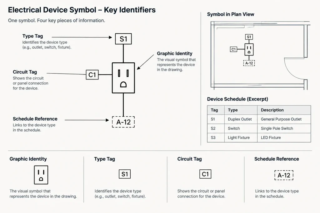
A device symbol and the text placed beside it often communicate different kinds of information. The graphic may identify a receptacle, luminaire, panel, or control device, while nearby text may identify a type, circuit, mounting condition, control zone, or schedule entry.
The legend should make this distinction clear. One effective approach is to show a representative symbol with sample tag positions, followed by a short explanation of each tag category. The samples should be generic and should not imply an actual project rating or circuit assignment.
For example, a legend may explain that one text field refers to a fixture type and another identifies circuiting. The fixture schedule then defines the type, while the panel schedule and plans carry the circuit relationship. This prevents the legend from becoming a second, conflicting schedule.
Document Graphic Variations Carefully
Small graphic changes can carry important meaning. A filled symbol, diagonal mark, surrounding box, dashed outline, or added letter may identify a special condition. If those variations appear in the plans, the legend should explain them consistently.
Common variation categories include:
- Normal, backup, or other source-related designations
- Existing, new, relocated, removed, or future work
- Surface, concealed, exposed, or underground routing
- Single-device and multi-device arrangements
- Controlled and uncontrolled device conditions
- Floor, wall, ceiling, roof, or equipment-mounted locations
Do not rely on color alone to communicate these differences. Drawings may be printed in monochrome, screened, reduced, or viewed on devices with different display settings. Pair color with line type, fill, text, or another reproducible graphic convention where appropriate.
Control Master Legends Without Publishing Everything
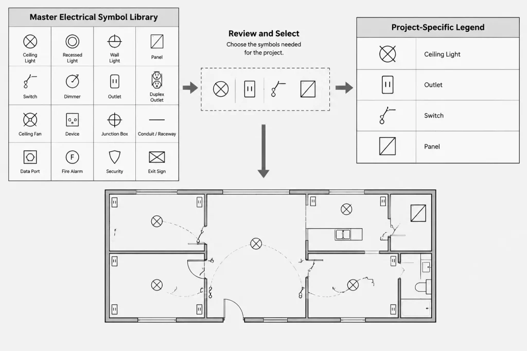
Many CAD libraries contain a master symbol legend with entries accumulated across numerous project types. That master can be a useful source, but it should not automatically become the issued project legend. Publishing unused symbols makes the reader wonder whether missing devices were intended or whether the symbols apply somewhere outside the current view.
A controlled workflow can maintain two levels:
- Library-level legend: A broad internal reference associated with approved office blocks and naming conventions.
- Project-level legend: A selected set containing the symbols and conventions relevant to the issued drawings.
The project legend may include a limited number of symbols that are expected in later phases, but they should be reviewed deliberately rather than retained by habit. Every issued entry should have a reason to be present.
A Practical CAD Workflow
1. Establish project categories
List the electrical plan types and diagrams expected in the set. Use that list to define legend groups before placing individual entries.
2. Collect symbols from controlled sources
Insert symbols from the approved project or office library. Avoid harvesting blocks from unrelated drawings without checking their definitions, units, layers, and attributes.
3. Build a consistent row structure
Use a repeatable arrangement for the symbol sample, symbol name, plain-language description, and optional reference. Consistent spacing makes omissions and duplicates easier to detect.

4. Compare the legend with actual plan usage
Create a list of block names used in the project, either through CAD data tools or a structured manual review. Compare that list with the legend. Investigate symbols used on plans but absent from the key, as well as legend entries that never appear.
5. Review non-block graphics
Not every convention is a block. Check line types, circuiting arcs, home runs, boundaries, hatches, status graphics, and diagram connection marks. Include explanations when their meaning is not already clear elsewhere.
6. Coordinate descriptions with schedules and notes
Confirm that terminology matches the fixture schedule, equipment schedule, abbreviations, sheet notes, and diagram labels. Similar devices should not be described with competing names across the set.
7. Test the plotted result
Review the legend at the intended sheet output, in both full-size and reduced views where applicable. Confirm that symbol details, text, fills, and line types remain distinguishable.
Common Legend Problems
- Duplicate graphics with different descriptions: Readers cannot determine whether the devices are actually different.
- Different graphics with the same description: The distinction may be intentional, but it has not been explained.
- Unused legacy symbols: Entries copied from previous projects introduce false scope.
- Plan symbols missing from the legend: Custom or newly added blocks were not included in the documentation review.
- Descriptions that act like specifications: The legend contains technical promises that are not coordinated with schedules or project requirements.
- Unreadable samples: Dense symbols, small text, or weak lineweights fail when plotted.
- Uncontrolled manual edits: A legend symbol no longer matches its library or plan counterpart.
Final Coordination Check
Before issue, treat the electrical symbol legend as a coordination deliverable. Compare it with each plan type, review its terminology against schedules and notes, and verify that project-specific graphic variations are explained. Remove irrelevant entries and resolve symbols that appear under multiple names.
A good legend does not attempt to contain every project requirement. It provides a clear visual vocabulary and directs the reader toward the drawings, schedules, details, and diagrams that carry the remaining information. When managed as part of the CAD workflow, the legend becomes a reliable interface between the symbol library and the issued electrical drawing set.
Legend Governance and Revision Control
Legend quality depends on ownership as much as drafting. The project team should identify who may add symbols, revise descriptions, or change graphic conventions. Without that control, a block can be updated on the plans while an older representation remains in the legend.
Changes should be reviewed for effects beyond the legend itself. A revised symbol name, attribute, visibility state, or layer assignment may also affect schedules, extraction workflows, detail references, and drawing comparisons. Keeping the symbol library, project files, and issued key aligned reduces ambiguity during later revisions.
Use Descriptions That Support Drawing Interpretation
Legend descriptions should be concise enough to scan but specific enough to distinguish similar graphics. Prefer terminology already used in schedules, notes, and diagrams. Avoid adding product requirements, installation instructions, or performance claims that belong in other project documents.
Where a symbol has several project-specific states, explain the visual difference rather than repeating a broad device name for every entry. If added text determines the state, clarify what category that text represents and direct the reader to the corresponding schedule or plan information.
Audit the Legend as Drawing Data
A visual check alone may miss duplicate block definitions, inconsistent attributes, or symbols hidden within nested blocks. When the CAD workflow permits, compare the project legend with block inventories, attribute data, layer use, and actual plan instances. The goal is not merely to confirm that the graphics look alike, but that they remain connected to the intended drafting system.
- Check for symbols used on plans but absent from the legend.
- Identify legend entries that do not occur in the issued scope.
- Compare descriptions with schedule and diagram terminology.
- Review line types, hatches, boundaries, and connection marks that are not stored as blocks.
- Confirm that plotted graphics remain distinguishable without relying on color.
Keep the Legend Useful Through Project Changes
The legend should be reviewed whenever scope, equipment identification, plan categories, or drawing conventions change. A final review near issue is valuable, but routine coordination during drafting is more effective than correcting an accumulated list at the end.
Treating the legend as managed project data produces a clearer drawing key and makes discrepancies easier to find. It also supports a consistent relationship among CAD blocks, annotations, schedules, diagrams, and the plans where readers encounter them.
Electrical Symbol Legend FAQ
Should every symbol in the CAD library appear in the project legend?
No. The issued legend should generally reflect symbols and conventions relevant to the project. A broader office legend can remain an internal library reference.
Can the legend replace equipment or fixture schedules?
No. The legend explains graphic meaning. Schedules and related documents carry detailed equipment identification, characteristics, and coordinated project information.
Should legend symbols use the same CAD blocks as the plans?
Whenever practical, yes. Reusing controlled definitions reduces the risk that the plan and legend will show different geometry, attributes, layers, or visibility states.
How should similar symbols be distinguished?
Document the graphic feature or annotation that changes the meaning, such as fill, line style, added marks, status text, or mounting designation. Do not depend on color alone.
What should be checked before issuing the legend?
Compare it with actual plan usage, schedules, notes, diagrams, line-type conventions, and plotted output. Resolve missing symbols, unused entries, duplicate meanings, and inconsistent terminology.
Do all electrical drawing sets use identical symbols?
No. Conventions can vary by firm, client, discipline, and project. Readers should use the legend and coordinated project documents rather than assume that a familiar-looking graphic always has the same meaning.











Leave a Reply
You must be logged in to post a comment.