
Plan-to-one-line reconciliation connects the physical view of an electrical floor plan with the distribution logic shown on a single-line diagram. A disciplined cross-check helps reviewers distinguish genuine design-document conflicts from intentional differences in drawing scope and representation.
The workflow below focuses on traceability: identifying equipment, following its documented source, confirming its status, and checking the references that connect plans, diagrams, schedules, and details. It is intended for CAD coordination and drawing review, not as a replacement for engineering judgment, calculations, code evaluation, or field confirmation.
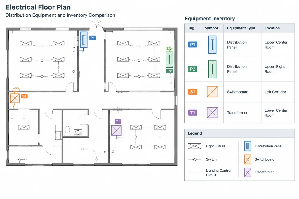
An electrical floor plan and a single-line diagram describe the same distribution system from different viewpoints. The plan shows where equipment and loads are located, while the one-line shows how power is distributed between sources, buses, feeders, protective devices, and major loads. When these drawings are developed separately, their information can drift apart.
Plan-to-one-line reconciliation is the process of comparing those views and confirming that each important item has a consistent identity, source, destination, status, and reference. This is not a substitute for engineering calculations, code review, or field verification. It is a drawing-control workflow that helps teams find documentation gaps before an issue set is published.
Why Floor Plans and One-Lines Commonly Diverge
Floor plans and one-lines often progress at different speeds. A designer may relocate a panel on the plan without updating its diagram label. A feeder may be rerouted because of architectural changes while its source-to-load relationship remains unclear. Vendor equipment may appear as a generic placeholder on one drawing and as several components on another.
Other common causes include:
- Equipment copied from an earlier project phase without updated identifiers.
- Panel or transformer names changed in only one drawing.
- Loads added to plans before distribution diagrams are revised.
- Future, existing, relocated, and new equipment shown with inconsistent status notation.
- One-line branches that terminate at equipment not found on any plan.
- Plan symbols that lack a source, circuit, feeder, or cross-reference.
- Separate CAD files edited by different team members without a coordinated review point.
The goal is not to make the two drawings look alike. Their graphic purposes are different. The goal is to make their shared information agree.
Define the Shared Coordination Fields
Before reviewing graphics, identify the data that should remain consistent across the drawing set. A simple reconciliation matrix can provide a controlled place to compare that information.
| Coordination field | Floor plan evidence | One-line evidence | Review question |
|---|---|---|---|
| Equipment identifier | Tag beside the equipment symbol or footprint | Label at the diagram node | Is the same identifier used in both locations? |
| Equipment status | Layer, linetype, keynote, or local note | Diagram graphic or status note | Do existing, new, relocated, and future conditions agree? |
| Source | Circuit tag, feeder tag, or reference note | Upstream branch connection | Can the plan item be traced to the correct source? |
| Destination | Equipment location and plan label | Downstream node or load label | Does the branch terminate at the intended item? |
| Drawing reference | Detail, section, schedule, or diagram callout | Plan or schedule reference | Does the reference lead to a valid drawing location? |
| Feeder identity | Raceway or feeder annotation where shown | Branch or feeder annotation | Are naming and scope descriptions coordinated? |
Not every field must be repeated on every drawing. Excessive duplication creates another maintenance problem. Instead, decide which drawing owns each piece of information and where other drawings should use a reference.
A Practical Reconciliation Workflow
1. Freeze a Review Set
Compare drawings from the same issue state. Mixing a current floor plan with an older one-line can produce false discrepancies. Record the file dates, issue designation, or internal review milestone used for the comparison.
If the project uses external references, confirm that the referenced plan files are loaded from the intended locations. A seemingly missing panel may actually be present in an unloaded or outdated reference.
2. Build an Equipment Inventory from the Plans
Start with distribution equipment and other major electrically served items that should have a diagram relationship. Collect their displayed identifiers, locations, statuses, and available source references.
CAD block attributes or data extraction tools may speed up this step when blocks are structured consistently. However, automated output should be checked visually. Exploded symbols, plain-text labels, nested blocks, and inconsistent attribute names can cause equipment to be omitted or counted incorrectly.
3. Build a Diagram Node Inventory
Review the one-line from each source toward its downstream branches. List the labeled nodes and note how each is connected. Include diagram items that represent assemblies rather than physical equipment so they are not mistakenly treated as missing plan objects.
At this stage, separate true physical items from diagram-only concepts. A bus, splice point, or simplified branch may be essential to the one-line but may not require an independent floor-plan symbol.
4. Match by Identifier, Then Verify Context
An exact tag match is a useful starting point, but it is not enough. Confirm that the matched items also have compatible descriptions, locations, statuses, and upstream relationships. Reused identifiers can create a misleading match, especially when equipment has been copied between areas or project phases.
Where tags differ, avoid silently editing the first discrepancy found. Determine which document is authoritative, check related schedules and details, and then make a controlled correction across affected drawings.
5. Trace Source-to-Load Relationships
For each plan item, follow its documentation path back to a source. Depending on the drawing set, that path may pass through a panel schedule, feeder schedule, riser, or equipment connection note before reaching the one-line.
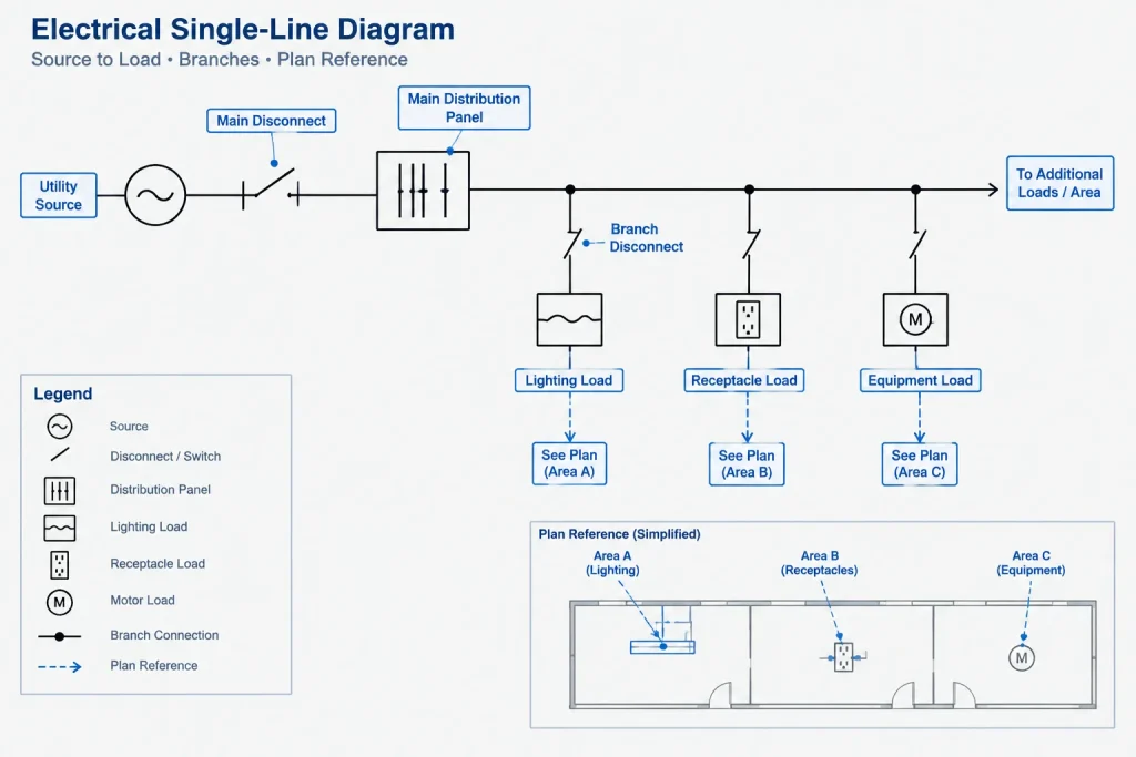
Flag any item that produces a dead end. Typical dead ends include a panel without an upstream source, a one-line feeder without a plan destination, or equipment with a circuit tag that does not correspond to the documented distribution hierarchy.
6. Review Drawing Status and Scope
Check that demolition, existing-to-remain, relocated, future, and new work are not accidentally blended. An existing panel shown on a new-work plan may still belong on the one-line, but its graphic treatment and notes should communicate the intended scope clearly.
Also distinguish project-designed work from vendor or by-others scope. A boundary note should not interrupt the basic documentation trail. The drawing set should still identify the interface, connection point, and responsible document where appropriate.
7. Log Discrepancies Instead of Marking Informally
Use a review log with a unique issue identifier, drawing reference, affected equipment tag, discrepancy description, assigned owner, and resolution status. This is more reliable than relying only on clouds or temporary CAD text.
Useful discrepancy categories include:
- Plan item missing from one-line.
- One-line item missing from plan.
- Identifier mismatch.
- Status mismatch.
- Source or destination mismatch.
- Broken or unclear cross-reference.
- Duplicate identifier.
- Unresolved vendor or by-others interface.
8. Recheck After Corrections
A correction can create a secondary inconsistency. Renaming a panel may affect its schedule title, circuit tags, feeder labels, detail notes, and equipment schedule entry. After revisions, repeat the source-to-load trace and verify all dependent references rather than checking only the original mark.
Using CAD Tools Without Hiding Judgment
CAD automation can support reconciliation, but drawing meaning still requires human review. Attribute extraction can identify tags, comparison tools can highlight changed geometry, and layer filters can isolate equipment categories. None of these tools can reliably determine whether two differently drawn objects represent the same design intent without a controlled data structure and informed review.
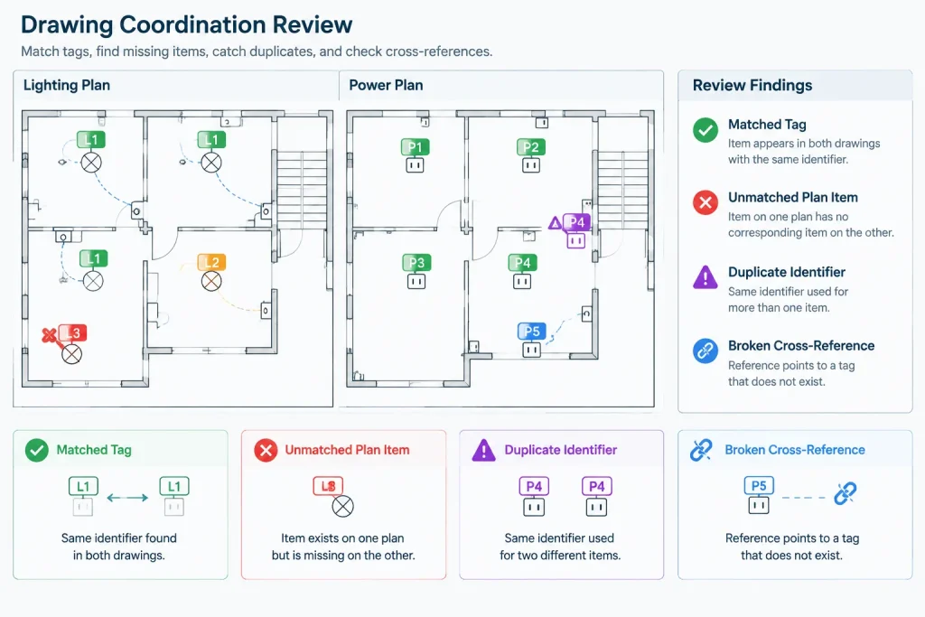
A useful workflow combines machine-assisted lists with visual inspection:
- Extract structured block data where available.
- Normalize obvious text formatting differences in a temporary review table.
- Compare plan identifiers against one-line identifiers.
- Investigate unmatched and duplicated entries visually.
- Confirm each correction in the source CAD files.
- Plot or publish a fresh review set before closing the check.
Do not alter project tags merely to make an automated comparison pass. The naming system should serve drawing clarity and project control, not the limitations of a spreadsheet or script.
Graphic Practices That Make Reconciliation Easier
Consistent drafting reduces the effort required for future reviews. Place equipment tags predictably, keep identifiers separate from descriptive notes, and avoid embedding critical identity data in unrelated text strings. On one-lines, maintain a readable source-to-load direction and keep labels visibly associated with the correct branch or node.
When a plan is crowded, a leader or keyed reference is preferable to moving a tag so far away that its ownership becomes ambiguous. When a one-line spans sheets, off-sheet references should preserve the destination identity and continuation path.
Shared naming rules are especially important. Similar-looking characters, inconsistent separators, and informal abbreviations can cause both human and automated matching errors. A project equipment list can serve as the naming authority, provided it is actively maintained rather than treated as a static export.
Final Review Checklist
- Plans and one-lines are from the same review state.
- Every major plan item expected on the diagram has been checked.
- Every physical one-line destination has a documented plan location or valid reference.
- Equipment identifiers are unique and consistently formatted.
- Source-to-load paths do not end without explanation.
- Existing, new, relocated, future, and removed conditions agree.
- Vendor and by-others interfaces remain traceable.
- Panel, feeder, equipment, and drawing references lead to valid destinations.
- Corrections have been checked against schedules, details, and related sheets.
- A fresh plotted or published set has been reviewed after updates.
Reconciliation as an Ongoing Drawing-Control Task
Plan-to-one-line reconciliation is most effective when performed at regular documentation milestones rather than postponed until the final review. Early checks expose naming and scope problems while they are still inexpensive to correct. Later checks confirm that design changes have propagated through the drawing set.
The result is not simply a cleaner one-line or a more complete floor plan. It is a more navigable electrical document set in which equipment can be followed from physical location to distribution source without guesswork. That traceability supports coordination, review, estimating, construction documentation, and future record updates.
How to Prioritize Reconciliation Findings
Not every discrepancy has the same effect on drawing usability. Review teams can prioritize findings according to whether they interrupt the documentation path, create conflicting identities, or affect only presentation.
- Traceability conflict: An equipment item cannot be followed from its plan location to a documented source or distribution branch.
- Identity conflict: The plan, one-line, schedule, or detail uses different identifiers for what appears to be the same item.
- Scope conflict: Status graphics or notes disagree about whether equipment is existing, new, relocated, future, or removed.
- Reference conflict: A callout leads to an incorrect, missing, or ambiguous drawing destination.
- Representation difference: The drawings use different graphics because one shows physical location and the other shows electrical relationships. This may be acceptable when identity and intent remain clear.
- Presentation issue: The information agrees, but tag placement, linework, or annotation makes the relationship difficult to interpret.
This classification helps prevent reviewers from spending equal effort on every mark. A broken source-to-load path generally requires coordination before a minor graphic cleanup, while an intentional diagram-only node may need only a clarifying note in the review record.
Establish Information Ownership
A reconciliation process works best when the project team identifies which document owns each data type. The one-line may control distribution relationships, while a floor plan controls physical location and a schedule carries supporting information. Other drawings can reference that information instead of repeating it unnecessarily.
Ownership does not mean a drawing can ignore conflicting information elsewhere. It defines where an approved correction begins and which dependent views must be checked afterward. Recording that decision in the discrepancy log also reduces repeated debate during later reviews.
Close the Loop in the Published Output
Corrections should be evaluated in the same form used by drawing recipients. CAD source files can appear coordinated while plotted lineweights, clipped references, annotation scales, or hidden layers make the published set unclear. A final visual review should therefore confirm both data agreement and readable presentation.
Keep the reconciliation record with the applicable review milestone. The log provides context for accepted representation differences, documents resolved conflicts, and gives later reviewers a starting point when the plans or one-line change again.
Frequently Asked Questions
Does every electrical plan symbol need a matching one-line node?
No. Floor plans can contain devices and local loads that are represented collectively or through schedules rather than as separate one-line nodes. The required match depends on the drawing set’s documentation structure. The important requirement is a clear path to the applicable source or distribution reference.
Should the floor plan or the one-line control an equipment identifier?
There is no universal answer. The project team should define an authoritative equipment list or document owner. Once ownership is established, corrections should be coordinated through every dependent plan, diagram, schedule, detail, and reference.
How should diagram-only items be handled?
Items such as buses, simplified connection points, and logical branches should be identified as diagram concepts rather than automatically logged as missing plan equipment. Reviewers should confirm that these elements support a traceable relationship to physical equipment where applicable.
Can CAD comparison software complete the reconciliation automatically?
Software can identify changed geometry, extract attributes, and compare structured identifiers. It cannot consistently interpret design intent, scope boundaries, or differences between physical equipment and diagram abstractions. Automated findings still require visual and contextual review.
What should happen when matching tags have different descriptions?
Treat the match as unresolved until the equipment context, location, status, source, and related schedules are checked. Identical tags can be duplicated or carried forward incorrectly, so text equality alone should not close the review item.
When is a reconciliation item ready to close?
Close an item after the approved correction appears in the source drawings, affected references have been checked, and the updated published output has been reviewed. The discrepancy log should record the resolution rather than relying only on removed markup.











Leave a Reply
You must be logged in to post a comment.