
Drafting site lighting plans in CAD requires more than arranging exterior fixture symbols on a civil background. The drawing must help readers trace each luminaire from its physical location to its fixture designation, electrical source, control relationship, route, and supporting detail.
The guidance below focuses on organizing that information without making the plan look like a wiring diagram or allowing electrical work to disappear beneath dense site geometry. It also explains how to coordinate poles, bollards, building-mounted fixtures, underground infrastructure, schedules, photometric material, and drawings produced by other disciplines.
A site lighting plan documents exterior luminaires and the electrical infrastructure that supports them. Depending on the project, it may include pole-mounted fixtures, bollards, wall-mounted luminaires, canopy lighting, landscape lighting, underground raceways, control zones, and connections to electrical distribution equipment.
The drafting challenge is that these elements must remain readable over a background containing roads, parking stalls, sidewalks, grading, utilities, planting, and property information. A useful site lighting plan therefore does more than place fixture symbols. It establishes clear relationships among fixture locations, circuit assignments, routing intent, controls, schedules, and related details.
Begin with the Correct Site Background
Use a coordinated civil, architectural, or landscape background rather than redrawing site geometry inside the electrical file. Confirm that the background uses the project coordinate system and that its insertion point, rotation, and units align with the electrical drawing environment.
Before drafting, review the background for information that affects electrical documentation:
- Building footprints, entrances, canopies, and loading areas
- Roads, curbs, parking spaces, sidewalks, ramps, and accessible routes
- Property lines, easements, and identified work limits
- Existing and proposed utilities
- Planting areas, trees, irrigation features, and site furnishings
- Grading information that may affect pole-base or equipment details
- Areas covered by enlarged plans or separate disciplines
Screen or simplify dense background information so electrical symbols remain prominent. Do not delete source information merely to improve appearance; control visibility through xref layers, layer states, or viewport-specific settings.
Separate the Plan into Documented Systems
A single exterior plan can become crowded when lighting, power, communications, and utility information are shown with equal emphasis. Decide whether site lighting will be presented on a dedicated sheet or combined with other site electrical work.
A dedicated lighting plan is often easier to review when the project includes many poles, control zones, or circuit routes. A combined plan may be appropriate when the site is small and the resulting drawing remains legible. In either case, use a clear layer structure so fixture symbols, tags, circuiting, controls, raceways, notes, and existing conditions can be isolated.
Place Luminaires Using Coordinated References
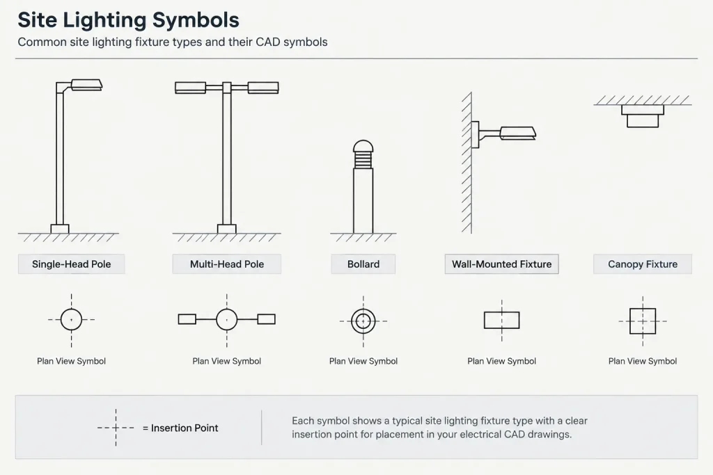
Pole-mounted fixtures
Represent each pole with a consistent plan symbol and an insertion point that corresponds to the intended pole centerline or another documented reference point. The symbol should distinguish the support location from the fixture head arrangement without attempting to reproduce unnecessary product geometry.
Where a pole carries multiple heads, show their general orientation when that information affects lighting distribution or coordination. Keep the graphic simple enough to read at the plotted site-plan scale. If exact arm configuration is important, reference an elevation, schedule, or mounting detail.
Bollards and low-level luminaires
Bollards and similar fixtures can be difficult to distinguish from site furniture or landscape symbols. Use a recognizable electrical symbol, fixture-type tag, or both. Coordinate locations with sidewalk edges, planting limits, gates, and maintenance access rather than relying only on visual spacing in CAD.
Building-mounted exterior fixtures
Wall-mounted and canopy fixtures should be tied to the building background and coordinated with architectural elevations or reflected ceiling information. The plan can communicate horizontal location and fixture identity, while elevations or schedules document mounting relationships and orientation where required.
Create a Consistent Fixture-Tagging Method
Fixture tags should connect every plan symbol to the appropriate lighting fixture schedule. A short type designation is usually easier to read than a long fixture description placed beside each symbol. If identical fixture types have different mounting arrangements, optics, finishes, controls, or accessories, the tagging structure should make the distinction visible.
Place tags consistently and avoid covering curbs, parking striping, property information, or other fixture symbols. Leaders may be used where direct placement is ambiguous, but excessive leaders can make a site plan harder to follow. Where repeated fixtures share the same type, establish a documented convention rather than assuming that an unlabeled symbol will be understood.
Show Circuiting Without Turning the Plan into a Wiring Diagram
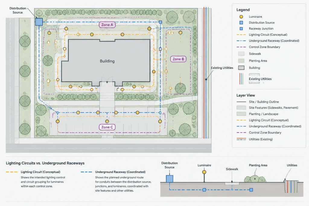
Site-plan circuiting should communicate design intent and drawing relationships, not every physical bend or installation decision. Circuit arcs, polylines, home-run marks, or raceway routes may be used depending on the project documentation method.
Whichever method is selected, identify the source panel or distribution equipment and the associated circuit reference. Distinguish branch-circuit graphics from physical underground raceway routing when both appear on the same sheet. Otherwise, a reviewer may interpret a conceptual circuit line as an exact trench route.
When several luminaires are grouped, verify that the circuit path does not appear to connect unrelated symbols simply because the line passes through them. Use connection points, controlled gaps, offsets, and readable home-run annotations to clarify continuity.
Document Underground Routing as Coordinated Intent
Underground raceways may be shown diagrammatically or as coordinated routes. State or graphically establish which approach the plan uses. A coordinated route should consider conflicts visible in the available backgrounds, including storm drainage, water utilities, sanitary utilities, retaining walls, foundations, tree zones, and paved surfaces.
Use separate linetypes or layers for proposed and existing work. Raceway tags can reference a conduit or cable schedule when route-specific information would overcrowd the plan. Where a route continues beyond the visible area, use a clear continuation reference instead of allowing the line to terminate without explanation.
Detailed trench, sleeve, penetration, and pole-base requirements belong in referenced details or sections. The plan should direct the reader to those views without duplicating their content.
Coordinate Lighting Controls
Exterior lighting may be divided into control zones based on operating intent, location, or connection to a particular control device. The CAD plan should make those relationships traceable without embedding an entire control sequence beside each fixture.
Possible documentation methods include:
- Control-zone boundaries or zone labels
- Fixture tags that include a control designation
- Control lines connecting luminaires to devices
- Keynotes referencing a written sequence of operation
- A control diagram linked to the plan by matching identifiers
Show control devices at their relevant location when spatial coordination matters. Devices located within electrical equipment may instead be represented on a diagram or schedule. Keep power circuit identifiers separate from control-zone identifiers so the two are not mistaken for one another.
Coordinate the Plan with Photometric Information
A photometric calculation plan and a construction-oriented site lighting plan serve related but different purposes. The photometric view typically emphasizes calculation points, results, fixture orientation, and modeled conditions. The electrical plan emphasizes installation references, circuiting, controls, routing, and drawing coordination.
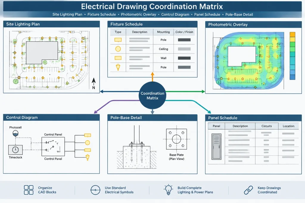
Check that fixture quantities, type designations, locations, and orientations agree between the two documents. If calculation graphics are imported into CAD, place them on dedicated layers and avoid allowing dense result text to obscure electrical annotations. A calculation background should not be treated as a substitute for circuit and control documentation.
Build a Useful Site Lighting Schedule
The fixture schedule should use the same identifiers shown on the plan. Include only verified project information and avoid converting preliminary selections into apparently final data. Schedule fields may address fixture description, mounting condition, source characteristics, control relationship, and remarks, depending on the project workflow.
Additional schedules may be appropriate for poles, control devices, or underground raceways. Avoid repeating the same information in several locations unless there is a clear coordination purpose. Repeated data can drift apart during revisions.
Reference Details and Enlarged Views
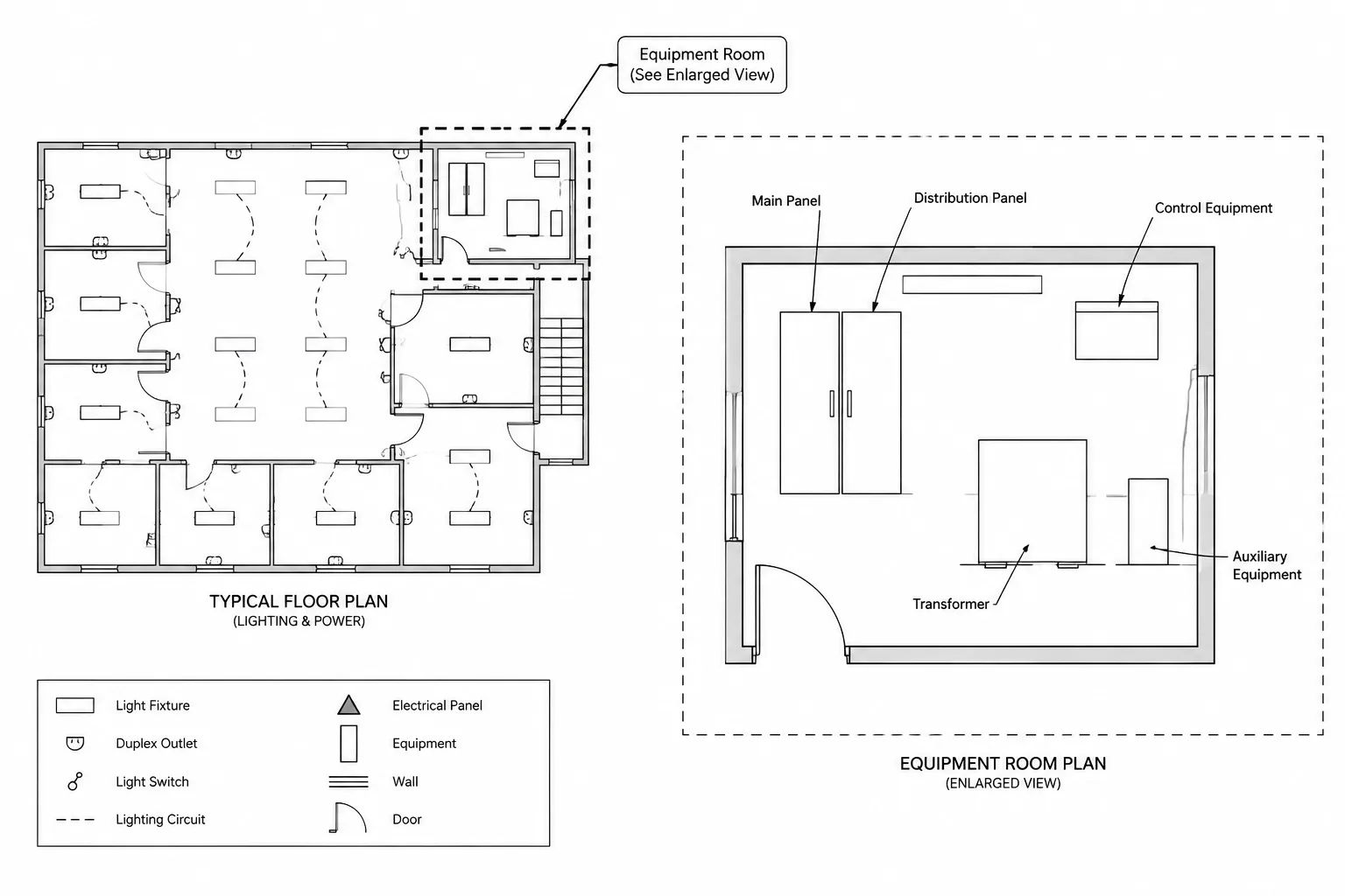
Use detail callouts where the plan alone cannot communicate the required relationship. Common subjects include pole-base arrangements, grounding diagram references, handhole relationships, building entries, equipment interfaces, and mounting configurations.
Do not assume that one generic detail applies to every fixture. Different site conditions may require different documentation. Match each callout to the intended fixture or location and verify that the referenced view is present in the issued drawing set.
Recommended CAD Layer Organization
| Drawing content | Layer purpose | Drafting consideration |
|---|---|---|
| Fixture symbols | Primary lighting geometry | Keep visually prominent over the site background. |
| Fixture tags | Schedule references | Maintain consistent placement and readable text. |
| Circuit graphics | Electrical connectivity | Differentiate conceptual circuiting from physical routes. |
| Underground raceways | Routing coordination | Separate proposed, existing, and removal work. |
| Control graphics | Zones and device relationships | Avoid confusing control references with circuit numbers. |
| Notes and callouts | Instructions and view references | Keep annotation independent from imported backgrounds. |
| Photometric overlay | Calculation coordination | Control separately for editing and plotting. |
Perform a Cross-Drawing Quality Review
Before issue, compare the site lighting plan with the fixture schedule, panel schedules, single-line diagram, control documentation, details, and photometric material. The review should confirm more than fixture count.
- Every visible fixture symbol has an understandable type reference.
- Fixture types used on the plan appear in the applicable schedule.
- Panel and circuit references agree with distribution documents.
- Control zones and device identifiers are consistent across views.
- Pole and bollard locations do not visibly conflict with site features.
- Underground routes have clear origins, destinations, and continuations.
- Existing, new, relocated, and removed elements are distinguishable.
- Detail and sheet references point to the correct drawing locations.
- Annotation remains readable at the intended plotted scale.
A well-drafted site lighting plan provides a reliable navigation layer between several disciplines and drawing types. By separating fixture identity, electrical connectivity, physical routing, controls, and calculation information, the CAD file remains easier to edit, review, coordinate, and issue.
Manage the Drawing as a Coordination Record
A site lighting CAD file should preserve the difference between information owned by the electrical discipline and information received from consultants. Keep referenced site geometry separate from electrical symbols and annotations so background updates do not overwrite design content or force extensive redrafting.
When an updated background is received, review more than its file date or visible outline. Check whether roads, curbs, planting areas, utility routes, building entrances, grading features, or property information have moved relative to the lighting layout. A background can appear generally unchanged while containing local revisions that affect individual poles, bollards, raceways, or equipment connections.
Establish Graphic Hierarchy Before Final Annotation
Test the plan using the intended plot settings before completing tags and leaders. Fixture symbols, circuit references, route graphics, and control identifiers should remain distinguishable when the site background is screened. Color differences visible in the CAD workspace may not provide sufficient separation in the issued drawing.
Use lineweight, linetype, symbol form, text placement, and layer visibility together. Avoid relying on only one graphic property to distinguish conceptual circuiting from physical raceway routing. The legend should explain any convention that would not be evident to a reader unfamiliar with the working file.
Control Ownership of Repeated Information
Assign a primary location for each category of project information. The plan can own location and connectivity, the fixture schedule can own fixture descriptions, the control documentation can own operating relationships, and details can own installation geometry. Matching identifiers connect these views without requiring the same note to be maintained in several places.
Where information must be repeated, include it in the revision review. A changed fixture designation, circuit source, control zone, or detail reference can affect several documents even when the visible site location remains unchanged.
Prepare the File for Review and Future Editing
- Use stable block insertion points that represent documented placement references.
- Keep tags and leaders independent from referenced background objects.
- Avoid exploding symbols merely to adjust their appearance in one location.
- Separate calculation overlays from construction annotations.
- Use consistent identifiers across plans, schedules, diagrams, and details.
- Record unresolved coordination items rather than disguising them with graphic adjustments.
- Check that frozen or hidden layers do not contain information required for issue.
The final drawing should allow another technical user to understand what each symbol represents, where its supporting information is located, and which relationships still require coordination. Project-specific design decisions and field conditions should be verified by the responsible professionals before the documents are issued or used for construction.
Frequently Asked Questions
Should a site lighting plan show exact underground raceway paths?
That depends on the documentation approach. A route may represent general connectivity or a coordinated physical path. The drawing should make the intended meaning clear and should not present a conceptual line as surveyed or installation-ready geometry.
How should pole-mounted luminaires be represented in plan view?
Use a consistent symbol with a meaningful insertion point, such as the documented pole centerline. Show fixture-head orientation when it supports coordination or interpretation, while reserving detailed mounting geometry for schedules, elevations, or details.
Are circuit identifiers and control-zone identifiers interchangeable?
No. A circuit reference identifies the electrical source relationship, while a control-zone identifier communicates operating grouping or control intent. Distinct graphic and annotation conventions help prevent readers from confusing them.
Can photometric results replace the electrical site lighting plan?
No. Photometric material supports evaluation of modeled lighting conditions, but it does not normally replace circuit references, control documentation, routing intent, schedule coordination, or construction-detail callouts.
How can dense civil backgrounds be made easier to read?
Control background visibility with referenced-file layers, layer states, screening, and viewport settings. Preserve source information while reducing its visual priority behind electrical symbols and annotations.
What should be checked after a site background is updated?
Review fixture locations, pole clearances, bollard relationships, underground routes, building interfaces, utility conflicts, control-device locations, and annotation placement. Also confirm that the coordinate system, units, insertion point, and rotation still align.









Leave a Reply
You must be logged in to post a comment.