
Electrical drawing note hierarchy is a scope-control system as much as a page-layout choice. It helps the drafting team place each instruction where readers are most likely to find it without making the requirement appear broader than intended.
This reference explains how general, plan-type, sheet, keyed, and local notes work together in an electrical CAD set. It also addresses note ownership, repetition, revision control, and coordination with symbols, schedules, diagrams, and graphic information.
Electrical notes explain requirements that symbols and linework cannot communicate by themselves. They can define drawing conventions, clarify scope, identify coordination needs, or describe a condition at one particular location. When every note is placed at the same level, however, the drawing set becomes difficult to read and maintain.
A practical electrical drawing note hierarchy assigns each instruction to the narrowest appropriate level. Broad requirements belong in general notes, plan-type rules belong with the applicable discipline or series, sheet-specific information stays on the relevant sheet, and location-specific instructions remain close to the affected work. This structure helps reviewers understand where a requirement applies and helps CAD teams avoid repeating the same text throughout a project.
Why note hierarchy matters
Notes have both content and scope. A technically clear sentence can still create confusion if the reader cannot determine whether it applies to the entire project, one electrical system, one sheet, or one device.
A well-organized hierarchy supports several documentation goals:
- Readers can find broad drawing conventions without searching every plan.
- Local exceptions are visible near the affected equipment or area.
- Repeated text can be revised from one controlled location.
- Sheet notes remain relevant to the view in which they appear.
- Conflicts between plans, diagrams, schedules, details, and notes are easier to identify.
- Copied notes from older projects are more likely to receive an intentional review.
The hierarchy is not a substitute for technical judgment. It is an information-management method that makes the intended scope of each note more apparent.
Common levels of electrical drawing notes
Project-wide general notes
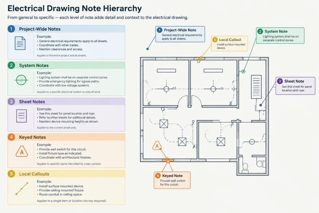
Project-wide notes communicate drawing conventions or broad requirements that apply across the electrical set. Typical subjects include coordination expectations, interpretation of existing conditions, document relationships, and general identification conventions.
These notes are often located on a cover, legend, or general-information sheet. They should be limited to genuinely broad information. A note that applies only to lighting plans or only to one renovation area is usually too narrow for this level.
System or plan-type notes
Some instructions apply to a defined group of drawings rather than the entire project. Examples include notes that govern lighting plans, power plans, site plans, single-line diagrams, or telecommunications drawings.
These notes can be placed on a series introduction sheet or repeated on the relevant sheets when each sheet may be issued or reviewed independently. The team should establish one deliberate rule rather than allowing inconsistent repetition.
A plan-type note should describe a convention shared by that drawing category. It should not be used to hide a unique field condition or equipment requirement.
Sheet-specific notes
Sheet notes apply to the content presented on one sheet. They are useful when an instruction affects multiple items in the view but has no purpose elsewhere in the set. For example, an enlarged electrical room plan may require coordination notes that are irrelevant to the overall floor plan.
Sheet-specific notes should remain visible without overwhelming the graphic area. A dedicated note column or an aligned note block usually reads more clearly than paragraphs scattered around a plan.
Keyed notes
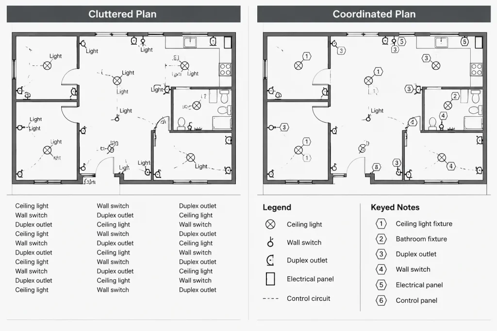
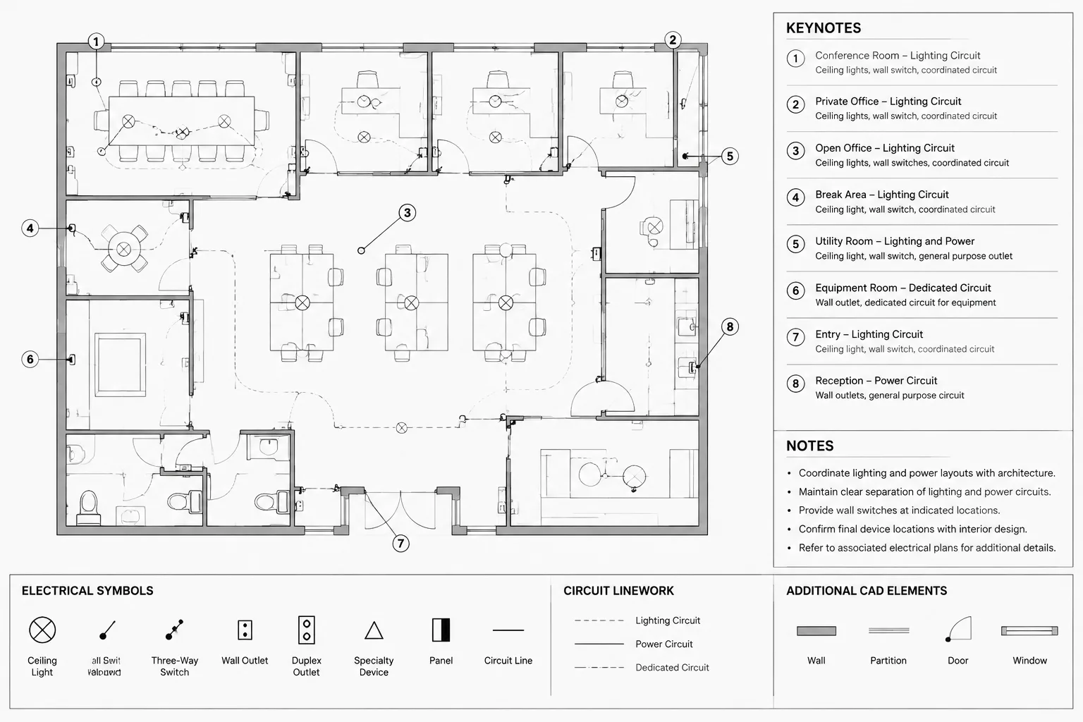
A keyed note connects a short identifier on the drawing to a corresponding note list. This approach is effective when several locations share the same instruction or when a full sentence would obscure plan geometry.
The identifier needs a clear relationship to its note list. Avoid creating one continuous project-wide sequence unless the team has a reliable method for controlling it. Sheet-based or view-based sequences are often easier to audit because the markers and definitions can be reviewed together.
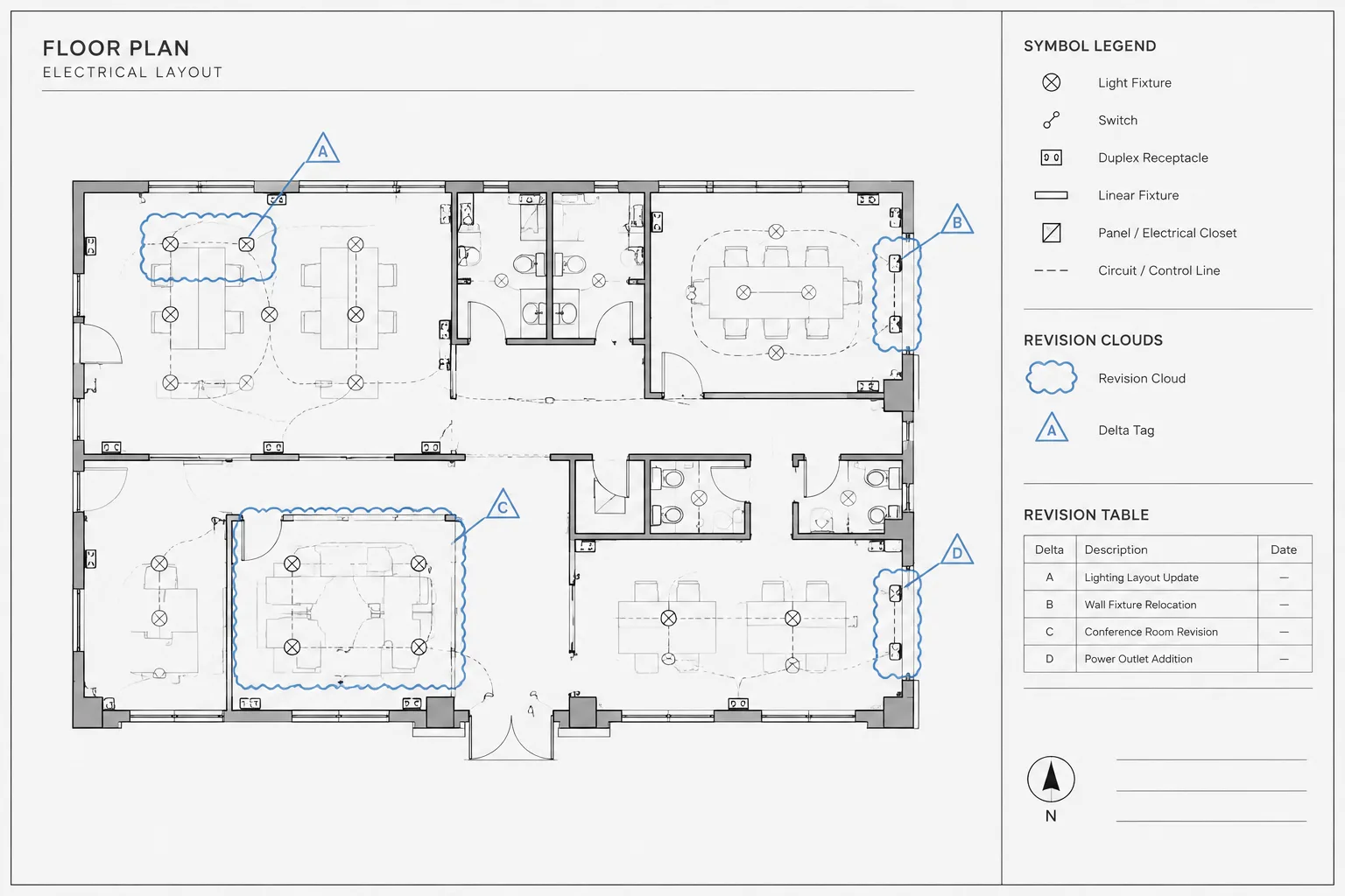
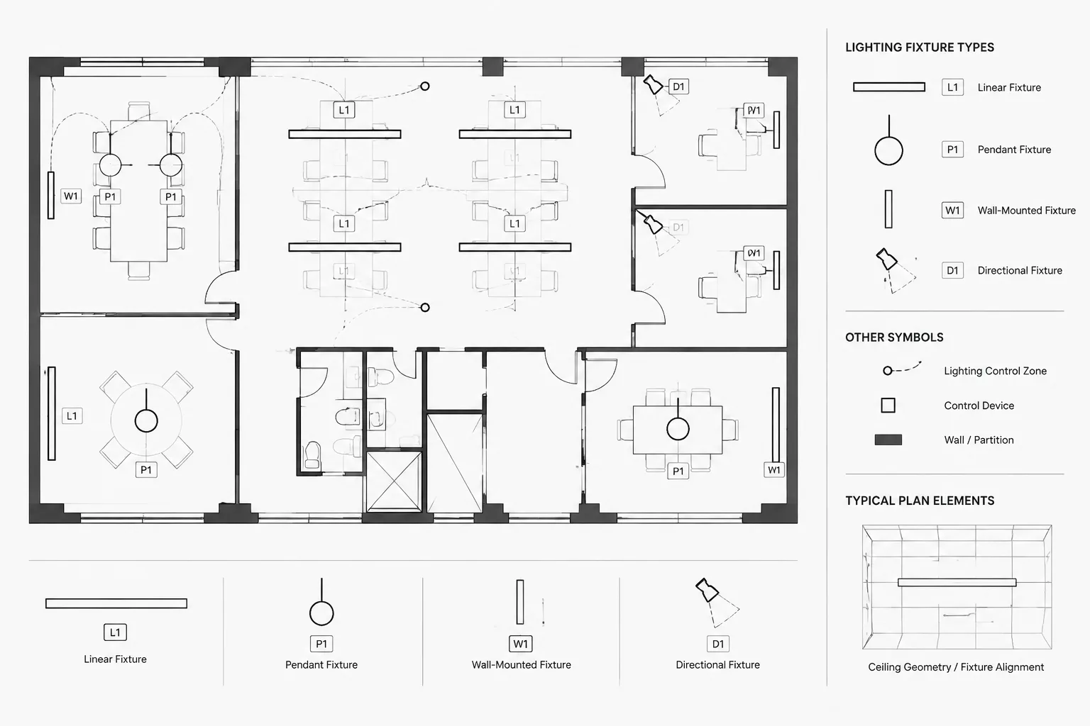
Keyed notes should not be confused with equipment tags, circuit identifiers, detail references, or revision markers. Each identifier type needs a visually distinct purpose.
Local notes and callouts
A local note points directly to one device, route, assembly, or condition. It is appropriate when the instruction is unique and unlikely to be reused. A leader should terminate clearly at the intended object rather than at an ambiguous group of lines.
Local notes are valuable for exceptions, but too many can make a plan difficult to scan. If the same local note appears repeatedly, consider converting it into a keyed note, a sheet note, or a symbol-based convention.
Choosing the correct note level
Start by asking where the instruction applies. The following decision pattern can help:
| Application | Preferred note level | Drafting consideration |
|---|---|---|
| Most or all electrical drawings | Project-wide general note | Confirm that the statement is truly universal. |
| One drawing type or system | System or plan-type note | Identify the affected plan category clearly. |
| Everything shown on one sheet | Sheet-specific note | Keep the note with the applicable sheet. |
| Several identified locations | Keyed note | Coordinate every marker with the note list. |
| One unique condition | Local note or callout | Use an unambiguous leader and attachment point. |
The narrowest appropriate level is usually the safest choice. Overly broad placement may make a note appear applicable where it is not. Overly narrow placement creates unnecessary repetition and increases the chance that one copy will become outdated.
Build notes as controlled CAD content
Separate formatting from technical wording
Use defined text styles, widths, spacing, and indentation so notes can be reformatted without rewriting their content. A consistent note block is easier to review than manually aligned text objects with slightly different settings.
Paragraph text is generally useful for wrapped notes, while attributes or structured data fields may help with identifiers and titles. The exact tool is less important than consistent editing behavior and predictable plotted output.
Assign note layers by function
A project may use separate layers for general notes, keyed-note markers, leaders, and local annotations. Functional separation supports visibility control and troubleshooting, but excessive layer subdivision can make editing cumbersome.
Layer names should follow the project CAD standard and remain understandable to recipients. Do not rely on color alone to distinguish note types because drawings may be printed or reviewed in monochrome.
Maintain a controlled source for repeated language
Frequently used notes should come from a reviewed source, such as a project template or office note library. Treat that source as a starting point rather than automatic project content. Every imported note should be checked for relevance, terminology, drawing references, and compatibility with the current scope.
When a repeated requirement is edited, search for uncontrolled copies elsewhere in the set. Similar wording in multiple locations may indicate that the note should be consolidated or linked to one authoritative location.
Prevent note conflicts and hidden requirements
Notes should support the drawings, not contradict them. A coordination review should compare note language with symbols, circuit tags, equipment identifiers, schedules, diagrams, and details.
Common conflict patterns include:
- A general note establishes one drawing convention while a legend shows another.
- A sheet note refers to equipment that was removed during design development.
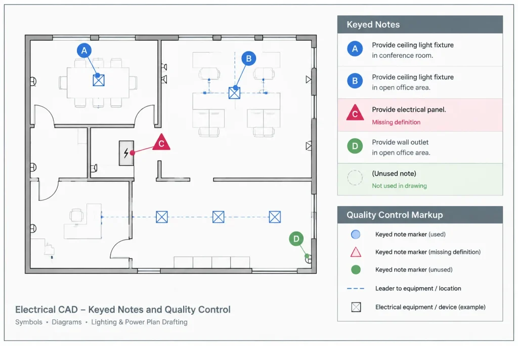
- A keyed-note marker remains on the plan after its definition is deleted.
- The same instruction appears in several places with different wording.
- A local note describes a typical condition even though visible exceptions exist.
- A note attempts to resolve information that should instead be shown graphically or scheduled.
Specifications and drawings may have different contractual roles depending on the project. Avoid casually copying specification language into plan notes. If information belongs in another project document, coordinate the reference and confirm that the drawing note adds necessary value.
Use notes for exceptions, not as a substitute for drafting
A note should not be used to compensate for unclear linework. Routing intent, equipment relationships, system boundaries, and connection points should be represented graphically when practical. The note can then clarify what the graphic cannot show efficiently.
Likewise, avoid using a broad phrase to cover unresolved design decisions. If equipment selection, circuiting, or interface responsibility is still being coordinated, track that issue through the project workflow rather than concealing it inside a vague drawing note.
Note review workflow before issue
A focused note review can be performed separately from the general drawing check:
- List the note categories used in the set and confirm that each has a defined purpose.
- Review project-wide notes for statements that do not apply universally.
- Check system and sheet notes against the actual content of their drawings.
- Match every keyed-note marker to a definition and every definition to at least one intended marker.
- Inspect local leaders at the plotted scale for clear attachment and readable spacing.
- Search for duplicated phrases, obsolete room references, former equipment tags, and unresolved placeholders.
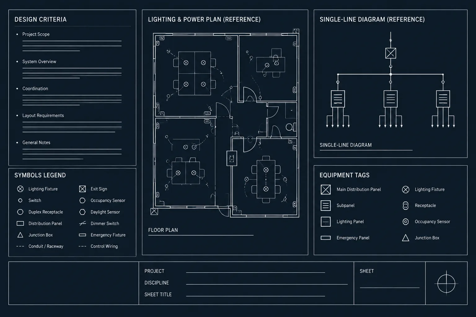
- Compare note terminology with legends, schedules, diagrams, and detail titles.
- Plot or export the sheets and verify that note columns, masks, lineweights, and text wrapping remain legible.
Automated searches and data extraction can assist with numbering and duplicate detection, but visual review remains necessary. A database may confirm that a note identifier exists while missing the fact that its leader points to the wrong object.
A practical hierarchy improves the whole drawing set
An effective electrical drawing note hierarchy tells the reader not only what an instruction says, but also where it applies. Broad conventions remain centralized, plan-type rules stay with their systems, sheet requirements remain local to their views, and unique conditions receive direct callouts.
This structure reduces clutter and makes revisions more controlled. More importantly, it encourages the drafting team to decide whether information should be shown as geometry, a symbol, a schedule entry, a diagram relationship, or a written note. That decision is central to producing electrical drawings that are clear, coordinated, and reviewable.
Apply a scope test before placing a note
Before selecting a note block or callout style, state the instruction without considering its current location. Then identify every drawing, view, system, or object to which it genuinely applies. That scope should determine the note level.
If the instruction remains valid throughout the electrical set, centralized placement may be appropriate. If its meaning changes with the sheet, system, or location, move it closer to the affected content. This test helps prevent a convenient template location from becoming an unintended statement of project-wide applicability.
Define note ownership and revision responsibility
Repeated language becomes difficult to control when no team member or drawing location is treated as authoritative. The CAD workflow should identify where shared wording originates, who reviews discipline-wide notes, and how revised language is checked against copied instances.
A useful review distinction is between content ownership and graphic placement. The person arranging a sheet may control alignment, wrapping, and leaders, while the responsible designer or reviewer confirms technical intent and scope. Keeping these responsibilities visible reduces the chance that editorial cleanup will accidentally alter meaning.
Check hierarchy during drawing changes
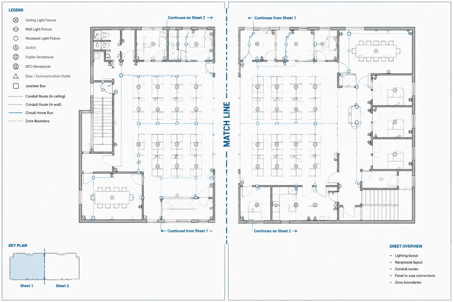
Note scope should be reconsidered whenever plans are divided, combined, reissued, or reorganized. A sheet note may lose its context when a view moves. A keyed note may become orphaned when geometry is deleted. A local exception may need a different treatment after the same condition appears elsewhere.
- Confirm that moved views retain every applicable note.
- Review note lists after markers are copied or removed.
- Check whether repeated exceptions have become a shared drawing rule.
- Verify that sheet titles and note wording still describe the same scope.
- Remove obsolete notes rather than leaving them hidden on frozen or nonplotting layers.
Keep note graphics subordinate to electrical information
Note blocks, leaders, and markers should be prominent enough to find but should not compete with equipment, routing, connection, or boundary graphics. Consistent text styles and marker families make the hierarchy recognizable without relying on decorative formatting.
When a drawing becomes crowded, moving prose into a controlled note list can improve readability. However, a remote note is only effective when its marker is easy to locate and its relationship to the affected object remains unmistakable.
Frequently asked questions
What is the difference between a general note and a sheet note?
A general note communicates a convention or requirement with broad applicability across the electrical drawing set. A sheet note applies only to the content or conditions presented on its sheet. If a statement is not valid elsewhere, placing it with the applicable sheet makes its scope clearer.
When should a local note become a keyed note?
Consider a keyed note when the same instruction applies at several identified locations or when full text would interfere with plan graphics. Keep a direct local callout when the condition is unique and the leader can clearly identify the affected object.
Should the same note appear on multiple sheets?
Repetition may be justified when sheets must remain understandable during separate review or issue. The team should still maintain an authoritative wording source and check every repeated instance after revisions. Uncontrolled duplication increases the risk of conflicting instructions.
How should note markers differ from equipment tags?
Each identifier family should have a recognizable visual role. Note markers, equipment tags, circuit identifiers, detail references, and revision symbols should not look interchangeable. Their shapes, prefixes, framing, or placement conventions can distinguish purpose without depending only on color.
Can notes replace missing drawing information?
Notes should clarify requirements that geometry, symbols, schedules, or diagrams cannot communicate efficiently. They should not conceal unresolved coordination or substitute for graphic relationships that readers need to see.
What should be checked when a note is copied from a template?
Review its applicability, terminology, references, affected systems, and relationship to the current drawings. Template language is a drafting resource, not proof that a requirement belongs in the project.

Leave a Reply
You must be logged in to post a comment.