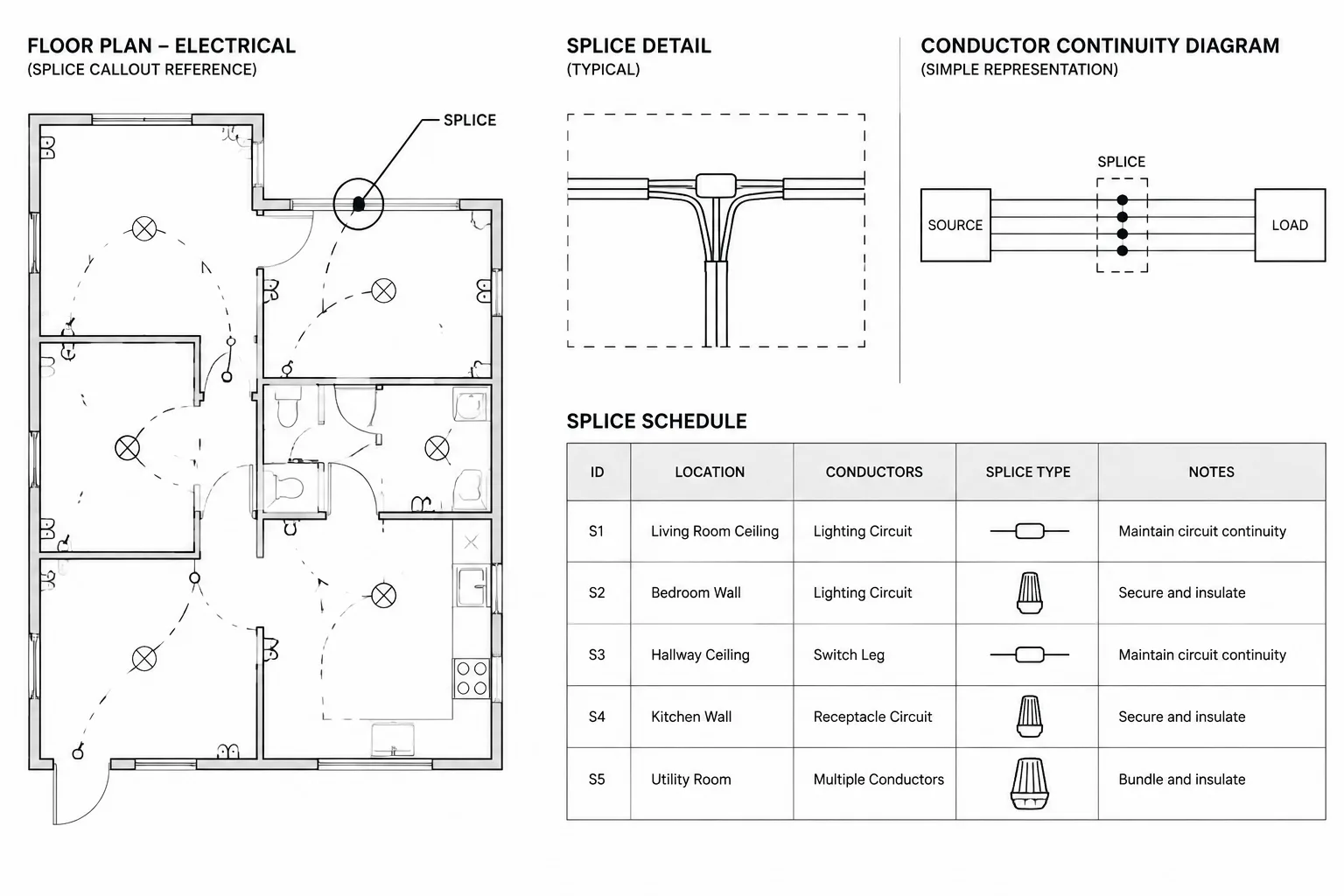
Electrical splice documentation in CAD must connect physical location, electrical continuity, and conductor identification without overloading a single drawing. A symbol on a plan may locate the splice, but related diagrams and schedules are often needed to explain what enters, what leaves, and which enclosure or route is involved.
This reference outlines a coordinated drafting method for splice tags, plan symbols, diagrams, schedules, block attributes, renovation status, and drawing review. It focuses on documentation structure rather than installation methods. Project-specific arrangements still require verification against the approved design information, specifications, equipment documentation, and applicable requirements.
Electrical splices can be difficult to document because they sit between several drawing systems. A splice may have a physical location on a floor or site plan, a logical position in a circuit diagram, conductor information in a cable schedule, and installation requirements in project notes or details. If these references are not coordinated, the drawings may show where a splice occurs without clearly identifying what continues through it.
Effective electrical splice documentation in CAD does not require every connection to be drawn at maximum detail. It requires a consistent method for identifying splice locations, preserving conductor continuity, and directing the reader to the appropriate supporting information. The drafting approach should match the project type, drawing scale, and level of design development.
What a Splice Symbol Should Communicate
A splice symbol is primarily a documentation marker. Its exact graphic form may vary by office standard, client requirement, system type, or drawing discipline. Regardless of appearance, the completed drawing should help the reader determine:
- Where the splice is located or approximately located.
- Which circuit, feeder, cable, or conductor group passes through it.
- Whether the symbol represents a planned splice, an existing splice, or a splice affected by renovation work.
- Where additional connection information can be found.
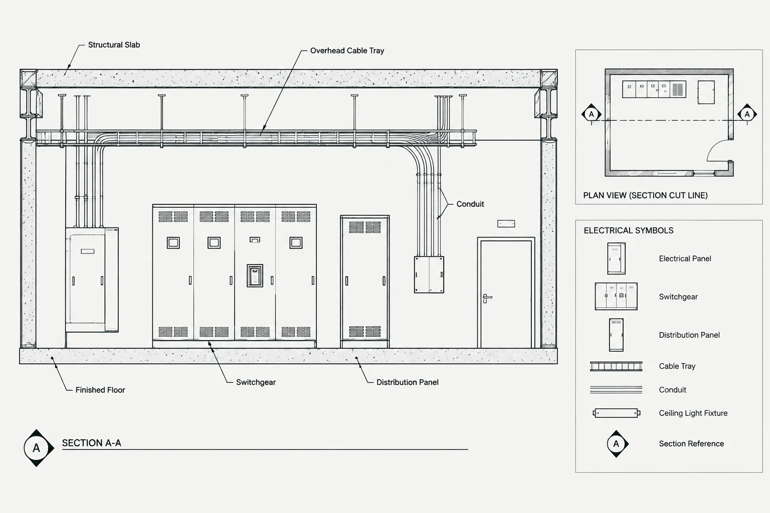
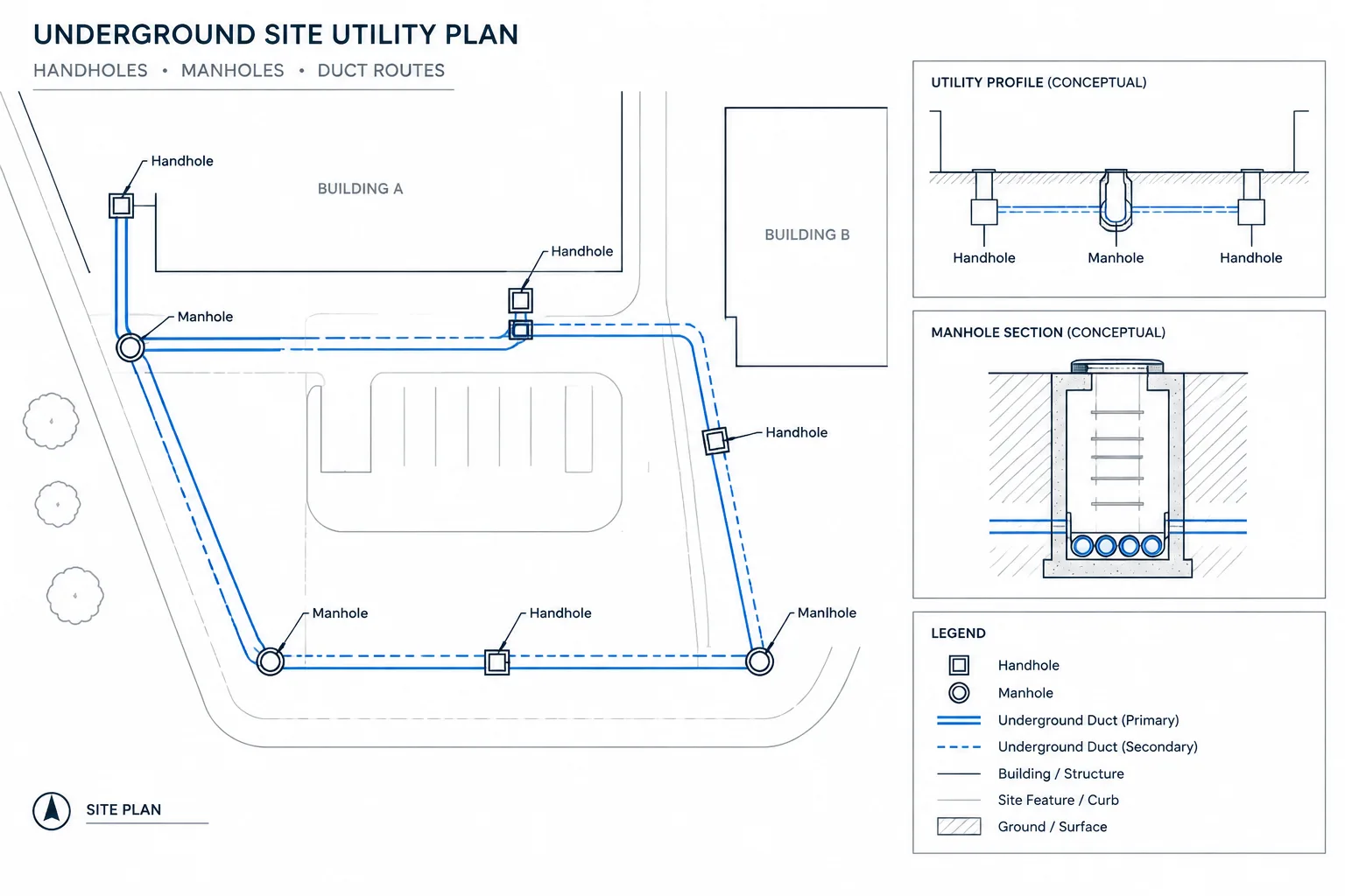
- Whether the splice is associated with an enclosure, handhole, pull box, vault, equipment terminal area, or other accessible location.
A generic dot or line junction is not always enough. In a schematic, a junction dot may simply show that lines are electrically connected. On a physical plan, a dedicated splice tag may be needed because location and enclosure coordination matter.
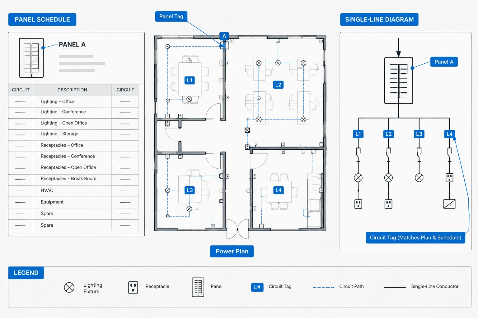
Choose the Right Drawing for Each Type of Information
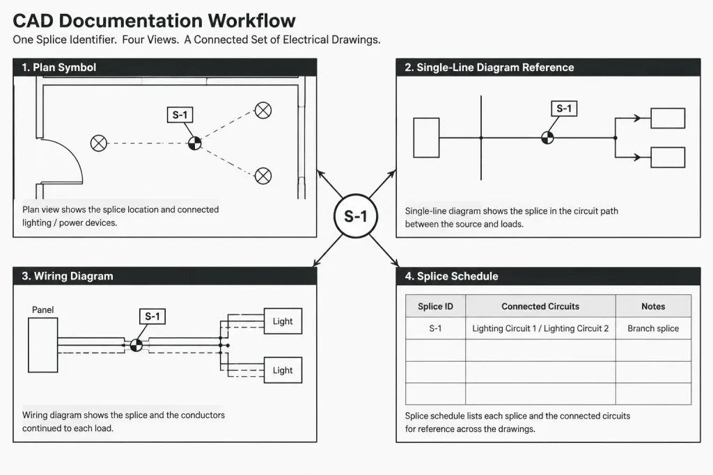
Trying to place all splice information on one plan often produces crowded notes and duplicated data. A better workflow separates physical, logical, and tabular information while connecting them through stable identifiers.
| Drawing or record | Primary purpose | Typical splice information |
|---|---|---|
| Floor or site plan | Show physical context | Symbol, splice ID, enclosure location, route association, and detail reference |
| Single-line diagram | Show distribution relationships | Splice position within a feeder or distribution path and related equipment tags |
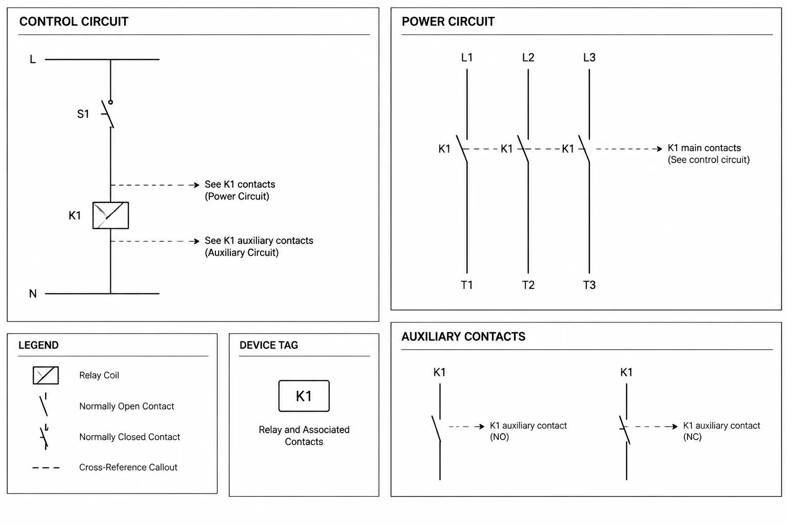
| Wiring or interconnection diagram | Show conductor-level continuity | Incoming and outgoing wire IDs, terminals, cable IDs, shields, and connection relationships |
| Splice detail | Clarify a repeated arrangement | Diagrammatic conductor grouping, identification method, and enclosure relationship |
| Splice schedule | Organize repeated data | Splice ID, location reference, circuits or cables, source, destination, and remarks |
The governing technical requirements must come from the verified project design, specifications, manufacturer information, and applicable requirements. A CAD block or typical detail should not be treated as proof that a splice arrangement is acceptable for a particular installation.
Create a Stable Splice Identification System
Each scheduled or cross-referenced splice should have a unique identifier. The tag should remain stable when viewports move, sheets are renumbered, or the splice appears in more than one drawing type.
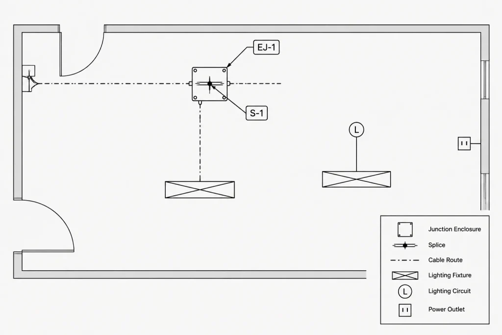
A useful tag structure can include a category prefix and a unique sequence or project designation. The specific format is less important than consistency. Avoid assigning multiple unrelated meanings to the same parts of a tag. For example, embedding a sheet number in the splice ID may cause unnecessary renaming when the drawing set is reorganized.
Separate identity from location
The splice ID should identify the splice itself. Its location should be recorded separately through a room name, grid reference, equipment association, plan callout, or schedule field. This separation allows the physical location to be revised without breaking every conductor reference.
Use one tag across all related documents
If a splice is labeled on a plan, single-line diagram, and schedule, use the same core identifier in each location. Additional suffixes may be appropriate when a drawing distinguishes separate conductor groups, but their meaning should be defined in the legend or notes.
Drafting Splices on Physical Plans
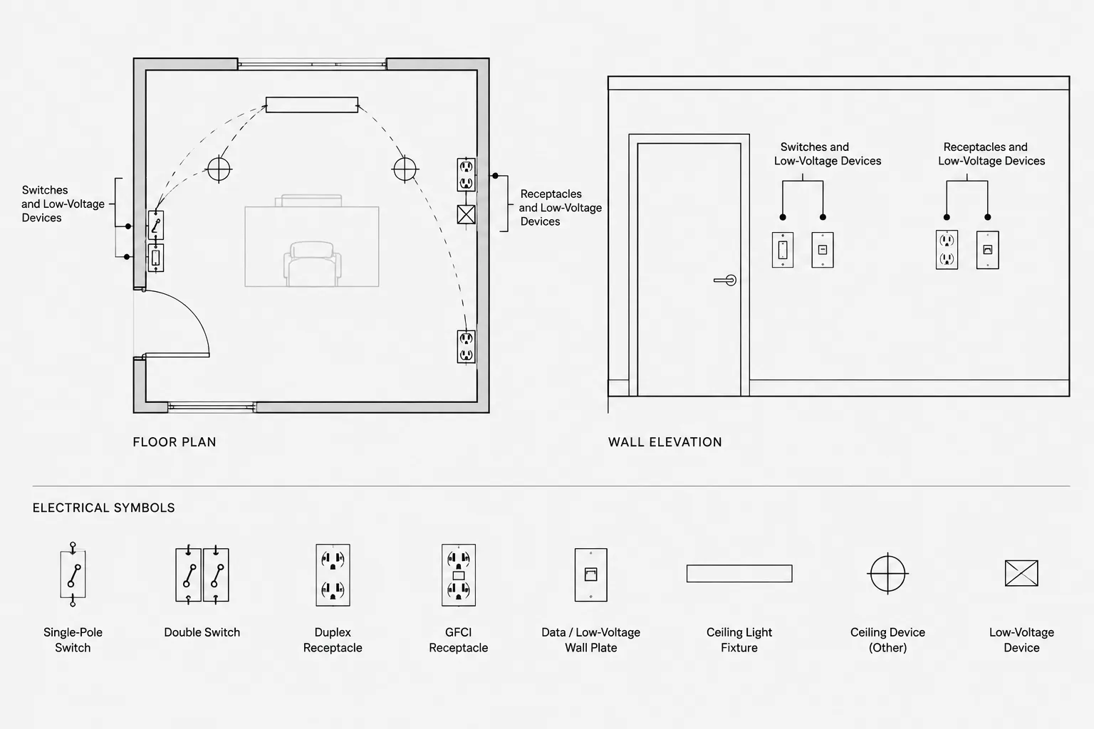
On a floor, roof, utility, or site plan, the symbol should be positioned to communicate physical intent without implying unsupported precision. If the splice occurs within a tagged enclosure, it may be clearer to tag the enclosure and reference the splice in a schedule rather than placing overlapping symbols at the same location.
Keep the symbol and its leader visually associated with the correct route. Where several circuits or cables share a pathway, do not assume that proximity alone establishes the relationship. Add a cable ID, circuit reference, route tag, or keyed note as needed.
For congested plans, place the splice tag in open space and use a leader with an unambiguous endpoint. Avoid crossing the leader through unrelated equipment, architectural text, or other routed systems. The plotted result should be reviewed because a readable model-space view can become unclear after screening and lineweight processing.
Showing Continuity in Diagrams
In single-line diagrams, a splice is normally shown at the appropriate logical point in the distribution path. The diagram should preserve a clear source-to-load reading direction and distinguish a documented splice from an ordinary line bend or line crossing.
Conductor-level diagrams require more explicit continuity. Incoming and outgoing wires or cable cores should carry identifiers that can be reconciled with cable schedules, terminal drawings, or field connection records. When an identifier changes through the splice, the diagram should show that transition intentionally rather than leaving the reader to infer it.
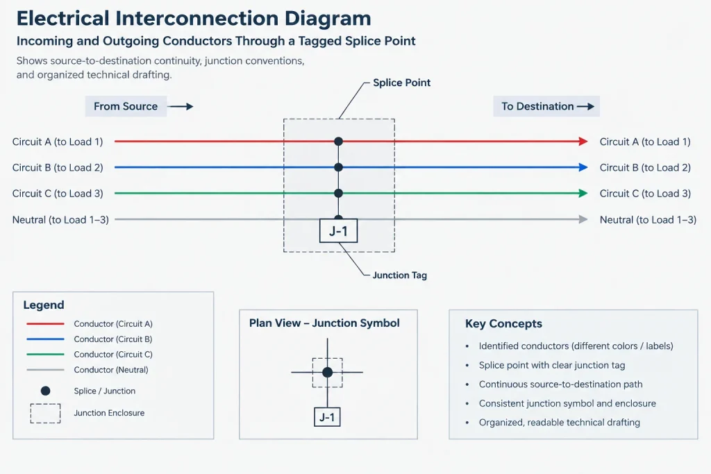
For control and communications circuits, also consider whether shields, drain wires, spare conductors, and grounding-related connections require separate representation. Their treatment should follow verified project requirements rather than assumptions built into a generic symbol.
Build a Useful Splice Schedule
A splice schedule is valuable when many splice points repeat across a project or when conductor relationships cannot be read comfortably from the plan. Schedule columns should be selected according to the documentation need, not simply copied from another project.
Possible fields include:
- Splice identifier.
- Drawing or location reference.
- Associated enclosure or equipment tag.
- Incoming cable, circuit, or conductor reference.
- Outgoing cable, circuit, or conductor reference.
- Source and destination references.
- System classification.
- Existing, new, relocated, or other project status.
- Related detail or diagram reference.
- Remarks requiring design-team confirmation.
Keep descriptive fields concise. Lengthy installation instructions are generally better placed in verified specifications or project notes. The schedule should help users locate and reconcile information, not become an uncontrolled substitute for the rest of the contract documents.
CAD Layers, Blocks, and Attributes
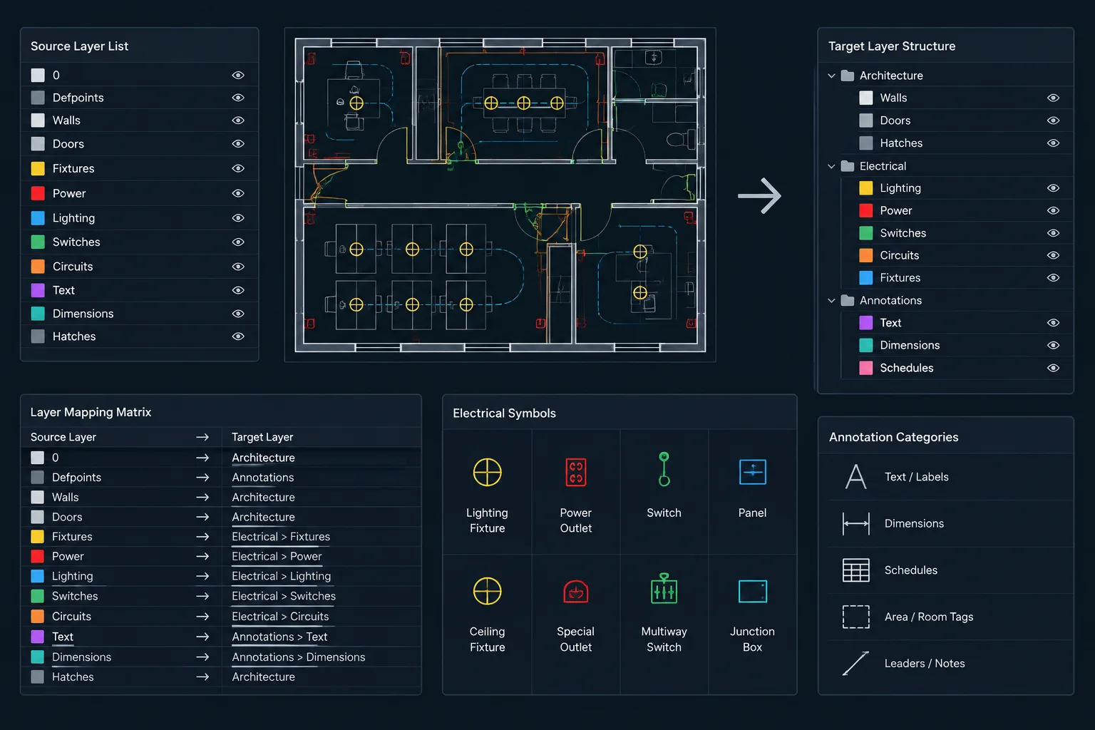
Place splice symbols, tags, leaders, and supporting linework on layers that fit the project layer structure. Separate layers can be useful when splice annotation must be displayed differently between construction plans, demolition plans, coordination views, and record drawings. However, excessive layer fragmentation can make visibility control harder to audit.
A reusable splice block may include attributes for the splice ID, circuit or cable reference, and status. Keep optional values independent so that blank attributes do not leave awkward gaps. If the block includes a leader, consider whether a separate annotation object would provide better flexibility in crowded plans.
Do not encode critical information only through color. Colors may change through plotting, exports, or external references. The printed symbol, tag, linetype, and note should remain understandable in monochrome output.
Renovation and Existing Splices
Renovation drawings require careful distinction between existing splices that remain, splices to be removed, and new connections created by rerouting. A general existing-condition graphic is not enough if the downstream circuit relationship changes.
Coordinate demolition and new-work plans so that conductor continuity is traceable across the transition. If an existing cable is cut back, extended, rerouted, or reconnected, the drawings should direct the reader to the relevant diagram or note without presenting unverified field conditions as confirmed facts. Unknown conditions can be identified for field verification using the project’s established notation.
Quality-Control Review
Before issuing the drawings, review splice documentation as a connected dataset rather than checking each sheet in isolation.
- Confirm that every scheduled splice appears in the referenced drawing or diagram.
- Check that every tagged plan splice has a corresponding explanation, schedule row, or detail where required.
- Trace source-to-destination continuity through each splice.
- Look for duplicate IDs and near-duplicate tags.
- Verify that cable, circuit, equipment, and enclosure identifiers match related schedules.
- Review existing and new-work status across all affected sheets.
- Check that symbols remain legible at the plotted scale.
- Confirm that line crossings, junction dots, and splice symbols cannot be mistaken for one another.
- Resolve placeholders and design-team review notes before issue.
A final PDF review is particularly useful because it reveals screening, masking, lineweight, and font problems that may not be obvious in the CAD editor.
A Coordinated Documentation Strategy
Clear splice documentation depends less on an elaborate symbol and more on disciplined coordination. The plan establishes physical context, the diagram establishes electrical continuity, and the schedule organizes repeated information. Stable identifiers connect those records.
When building or selecting CAD blocks for splices, treat them as components of this larger documentation system. Verify each symbol against the project legend, keep attributes aligned with schedules, and avoid using generic details as a substitute for project-specific engineering decisions. This approach produces drawings that are easier to review, revise, and interpret throughout the project lifecycle.
Managing Splice Information Through Revisions
Splice records should be treated as coordinated drawing data rather than isolated annotations. When a cable route, enclosure location, circuit designation, or project status changes, the revision may affect the plan, diagram, schedule, detail, and related notes. Updating only the visible plan symbol can leave conflicting information elsewhere in the drawing set.
Define the controlling record
The project team should identify which document controls each type of information. The plan may control physical context, while a wiring diagram controls conductor relationships and a schedule organizes cross-references. Defining that responsibility helps prevent the same information from being maintained independently in several places.
Use attributes as references, not hidden design data
Block attributes can improve consistency when they store splice IDs, cable references, or status labels. Critical relationships should still be visible in plotted documents or accessible schedules. Information that exists only inside an unprinted block attribute can be overlooked during review, export, or drawing exchange.
Review changes by identifier
A practical revision check starts with the splice identifier and follows it through every related record. Reviewers can compare its location, incoming and outgoing references, enclosure association, status, and detail callouts. This identifier-based review is more reliable than checking sheets independently because it follows the documented connection across drawing types.
Drawing Handoff Considerations
Before issuing or transferring CAD files, confirm that splice symbols do not depend on unavailable fonts, missing external references, unexplained color conventions, or office-specific content that another user cannot interpret. Include the required legend definitions and preserve readable attribute values when drawings are exported or plotted.
Record drawings require the same coordination discipline. Field-marked changes should be reviewed before they are incorporated as confirmed CAD information. Where conditions remain uncertain, use the project’s established verification notation rather than presenting assumptions as verified conductor continuity.
Frequently Asked Questions
Is a junction dot the same as a splice symbol?
Not necessarily. A junction dot usually indicates an electrical connection in a schematic or diagram. A splice symbol on a physical plan may also identify location, enclosure association, project status, and a reference to supporting documentation. The legend should define how each graphic is used.
Should every splice appear on the floor or site plan?
The required representation depends on the drawing purpose and project documentation method. A plan should show the physical context needed for coordination, while detailed conductor relationships may be clearer in a wiring diagram or splice schedule. The records should be connected by a stable identifier.
What is the difference between a splice schedule and a cable schedule?
A splice schedule is organized around connection points and their incoming and outgoing references. A cable schedule is generally organized around cables and their source, destination, or identification data. The records can reference each other, but they serve different documentation needs.
Should a splice ID include its sheet number?
Embedding a sheet number can create unnecessary renaming when sheets are reorganized. A stable splice ID is usually easier to coordinate when sheet, location, and drawing references are maintained separately.
How should an unknown existing splice be shown?
Use the project’s established notation for an unverified or field-confirmation condition. Do not depict assumed conductor relationships as confirmed facts. Coordinate the status across existing-condition, demolition, new-work, diagram, and schedule records as applicable.
Can color alone distinguish new and existing splices?
Color alone is unreliable because plotting, screening, exports, and external references may alter its appearance. Use readable tags, symbols, linetypes, notes, or other defined graphic conventions that remain understandable in monochrome output.
Leave a Reply
You must be logged in to post a comment.