
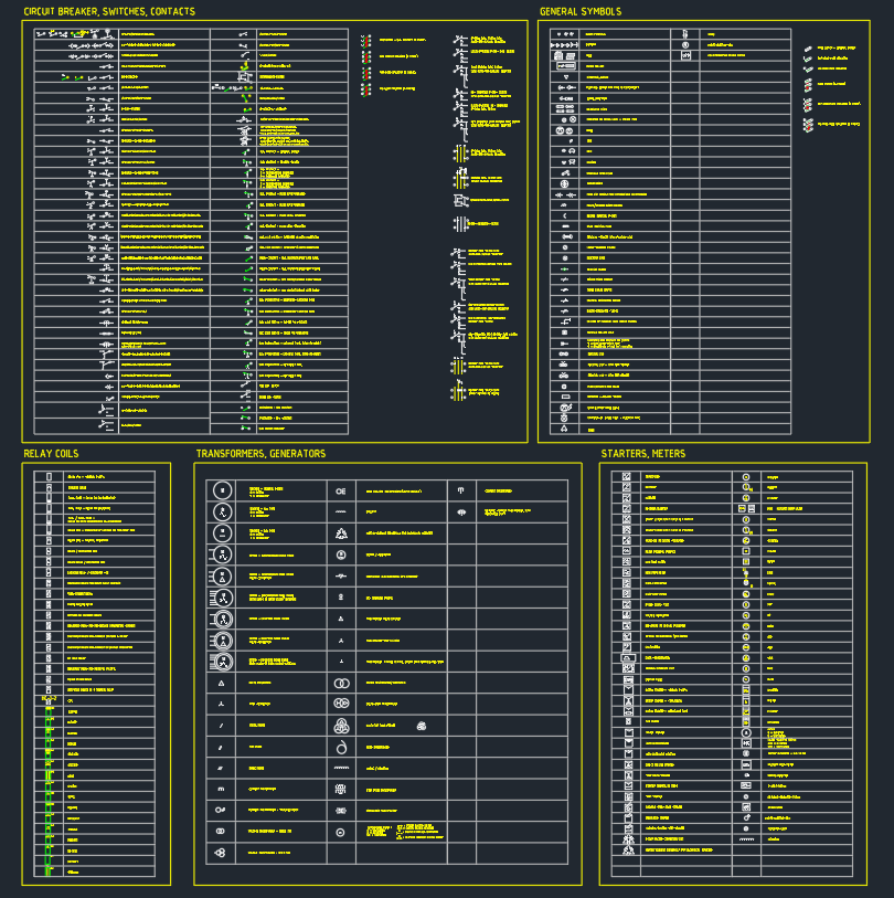
This thyristors symbols DWG provides a focused CAD resource for engineers, designers, and drafters preparing electrical schematic documentation. The file contains detailed thyristor representations that can be placed into circuit diagrams, control-panel drawings, and broader electrical design documentation.
Use the block as a drafting aid rather than as a substitute for a project symbol library or applicable engineering review. Before issuing a drawing, confirm symbol appearance, naming, orientation, and annotation conventions against the project legend and documentation requirements.
Discover a comprehensive DWG file featuring detailed *thyristors symbols* designed for use in electrical schematic diagrams. This high-quality CAD Block includes a variety of standardized thyristor representations, making it an essential resource for electrical engineers and designers. Perfect for circuit design, power electronics, and control panels, these symbols streamline drafting processes and ensure accuracy in professional projects. Fully compatible with AutoCAD and other major CAD software, this DWG file allows for seamless integration into your existing schematic layouts, providing versatility and ease of use for all your electrical design needs.
Please log in or register to download this file.
What this thyristor CAD block is used for
Thyristor symbols help communicate the intended role of a power-electronic device within a schematic. A consistent symbol makes it easier for reviewers and other design disciplines to identify devices, trace connections, and understand how the component fits into a control or power circuit.

This DWG is particularly useful when building or updating drawings for power electronics, control panels, and electrical equipment documentation. It can also support a reusable CAD library in which related device symbols are kept together and applied consistently across a drawing set.
Drafting considerations before placing the symbol
- Check the symbol against the project electrical legend and any office CAD standards.
- Use a consistent insertion orientation so the symbol reads clearly with connected conductors.
- Coordinate device tags, terminal references, and nearby notes with the project schematic.
- Keep the symbol separate from wiring, annotations, and other graphic elements so revisions remain manageable.
- Review the completed drawing for legibility, connectivity, and consistency before issue.
Related electrical CAD documentation
This resource fits naturally with electrical schematic symbols, single-line diagram concepts, control-panel layouts, equipment documentation, and electrical legends. Those related references can help establish how a downloaded block should be organized within a wider drawing package without changing the authoritative CAD content supplied with this page.
Working with the DWG file
The file is intended for use with AutoCAD and other major CAD software that supports DWG content. Import or open it within a controlled project workflow, then verify layer behavior, insertion settings, text styles, and plotting appearance before incorporating the symbol into issued documentation.

CAD drafting does not replace electrical design verification. Do not use a schematic symbol as permission to install, test, or modify an electrical circuit, and do not work on energized equipment. Installation and commissioning decisions should be handled by qualified personnel using the approved project documents.
Frequently asked questions
What does this DWG contain?
It contains a collection of detailed thyristor representations intended for electrical schematic diagrams and related CAD documentation.
Can the file be used in control-panel drawings?
Yes. The source content identifies control panels as a relevant application. Confirm the symbol, tags, notes, and connection details against the project standard before issuing a panel drawing.

Is this DWG limited to AutoCAD?
No. The source content states that the file is compatible with AutoCAD and other major CAD software. Compatibility should still be checked in the target drafting environment.
Should the downloaded symbol replace an electrical legend?
No. Treat it as a reusable drafting block. The project legend and applicable engineering requirements remain the basis for symbol selection and documentation.
Can this resource be used for circuit design?
It can support the graphic documentation of circuit designs, but the block itself does not verify circuit operation, ratings, protection, coordination, or installation requirements. Those matters require qualified engineering review.
Leave a Reply
You must be logged in to post a comment.