
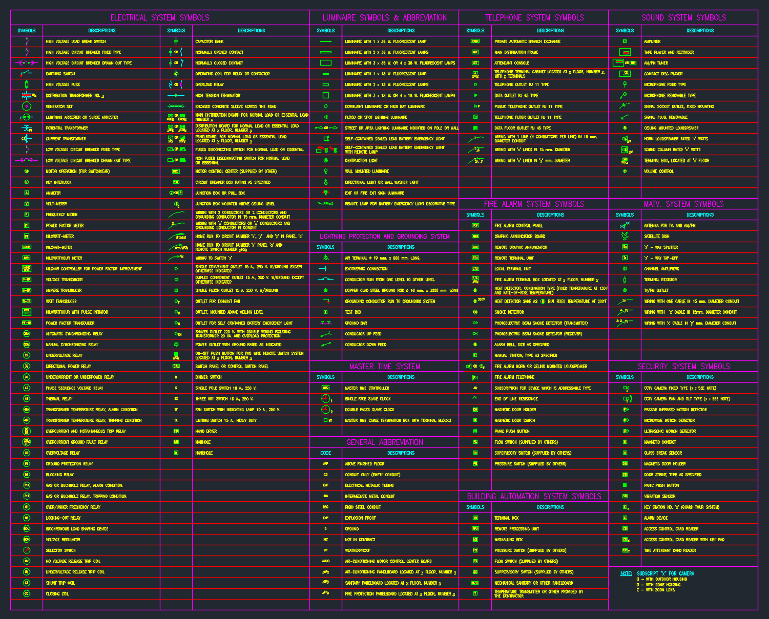
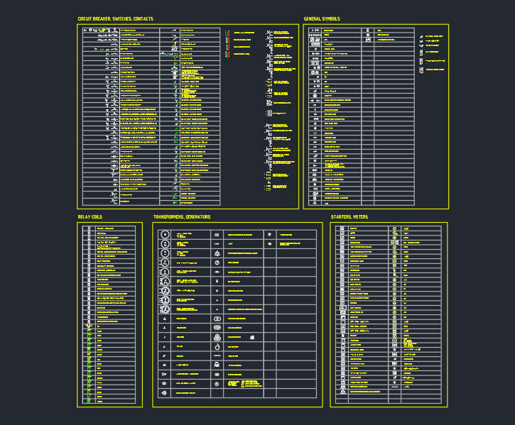
This schematic inductor symbols DWG provides a practical CAD reference for drafting circuit diagrams and electrical documentation. Reusable symbols help maintain visual consistency when components must be identified clearly across schematics, legends, and design packages.
Use the drawing as a starting point for your own documentation workflow. Before issuing a drawing, confirm that the selected symbol matches the component type, project conventions, and the notation used elsewhere in the electrical set.
Explore our comprehensive DWG file featuring a collection of schematic inductor symbols, essential for electrical and electronic circuit design. This CAD block is meticulously crafted for clarity and precision, making it ideal for engineers, architects, and students working on projects that require accurate inductor representations. Compatible with AutoCAD and other major CAD software, this file streamlines your workflow, saving valuable time in schematic diagram creation. Whether you’re designing PCBs or electrical layouts, these schematic inductor symbols ensure professional, standardized documentation for all your CAD projects.
Please log in or register to download this file.
How to use schematic inductor symbols in CAD drawings
Inductors are represented in schematics rather than as physical three-dimensional objects. Their symbols communicate the presence and connection of an inductive component within a circuit. In a CAD environment, the symbol should remain legible at the intended drawing scale and connect cleanly to wires, terminals, or other schematic elements.
Keep symbols consistent with the drawing set
A well-organized electrical drawing uses a consistent visual language. Check lineweight, layer assignment, insertion orientation, attribute treatment, and connection points against the project template or electrical legend. Consistency makes it easier for reviewers and designers to follow circuit relationships without interpreting each symbol independently.
Separate schematic documentation from physical layout
A schematic symbol describes circuit function and connectivity; it does not replace a physical component footprint, enclosure layout, or installation detail. When a project includes both schematic and equipment drawings, coordinate the component identifier and associated documentation between those views.
Useful CAD checks before issue
- Confirm that the symbol is inserted on the intended layer and uses the drawing’s established drafting conventions.
- Verify that connection points align with wires and do not create accidental gaps or overlaps.
- Review orientation and readability in the final plotted view, not only in the editing workspace.
- Use clear identifiers and cross-reference the symbol with the applicable circuit or equipment documentation.
- Keep the original download as a controlled reference if the block is edited for a project template.
Related electrical CAD topics
This resource connects naturally with schematic symbols, electrical legends, single-line diagram drafting, panel documentation, and CAD block management. Reviewing those related topics together can help establish a consistent workflow from circuit representation through equipment and distribution documentation.
Frequently asked questions
What is included in this DWG resource?
The source content describes a collection of schematic inductor symbols intended for use in electrical and electronic circuit design. Review the file after download to confirm the available blocks and their organization.
Can the file be used with AutoCAD?
Yes. The source content identifies the file as compatible with AutoCAD and other major CAD software. Compatibility can still depend on the software version, drawing settings, and the way the block is inserted into a project.
Are these symbols a substitute for a component footprint?
No. A schematic symbol communicates circuit representation and connectivity. A physical footprint or equipment layout serves a different documentation purpose and should be coordinated separately when required.
Should I edit the symbols before using them?
Edit them only when necessary to match an established project template or drafting convention. Preserve clear connection points and document any changes so the modified block remains understandable to other users.
Should symbol selection be checked by an engineer?
For issued project documentation, symbol selection and circuit representation should be reviewed by the responsible design professional. This CAD resource supports drafting but does not replace project-specific engineering review.




Leave a Reply
You must be logged in to post a comment.