
This logic gates symbols DWG provides reusable CAD graphics for creating and organizing digital logic schematics. The included gate types support common diagramming needs, while the editable drawing format helps drafters maintain consistent symbol placement, labels, linework, and spacing.
Use the source content and download control below to access the existing file. Before incorporating any symbol into formal documentation, compare its appearance and naming with the legend, drafting conventions, and project requirements used for that drawing set.
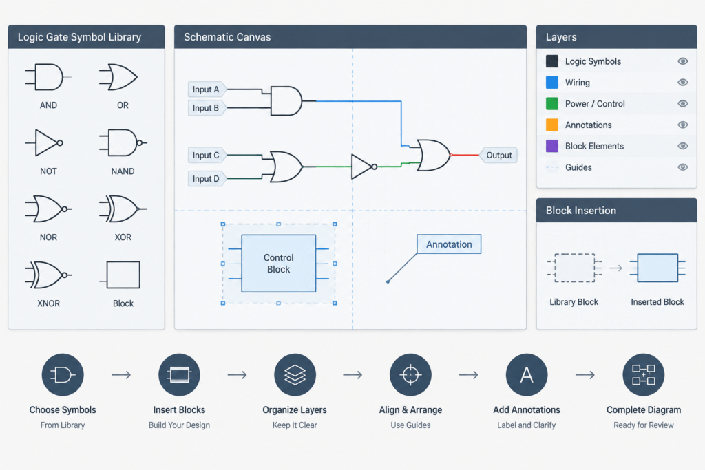
Download a high-quality DWG file featuring detailed Logic Gates Symbols, perfect for your next electrical or electronic circuit design project. This CAD Block includes standard symbols for AND, OR, NOT, NAND, NOR, XOR, and XNOR gates, ensuring your diagrams are clear and professional. Ideal for engineers, students, and architects, these logic gate symbols can be seamlessly used in AutoCAD and other CAD software, streamlining schematic creation and documentation. Enhance your workflow with accurate, ready-to-use logic gates for educational, industrial, or design applications.
Please log in or register to download this file.
What the logic gate symbols represent
Logic gates are graphical building blocks used to show how binary conditions are evaluated in a digital circuit or functional diagram. Each gate symbol identifies a logical relationship between its inputs and output. The CAD blocks communicate circuit intent, but they do not replace device data, connection details, or a project-specific design review.

Included gate types
- AND: Represents an output condition that depends on all required input conditions being present.
- OR: Represents an output condition that can result when an applicable input condition is present.
- NOT: Indicates inversion of a logic state and is also commonly described as an inverter.
- NAND: Combines an AND relationship with an inverted output.
- NOR: Combines an OR relationship with an inverted output.
- XOR: Represents an exclusive relationship in which the input conditions differ.
- XNOR: Represents the inverted form of XOR and is commonly associated with equivalent input conditions.
Using the DWG in a schematic workflow
After opening the file, review the block definitions, insertion points, text objects, line types, and assigned layers before copying symbols into another drawing. Matching the destination file’s layer naming, annotation style, and plotting setup helps prevent inconsistent graphics and unexpected output.
Place gate symbols so signal flow remains easy to follow. Keep connecting lines distinct from symbol outlines, avoid crowded intersections, and use clear labels for inputs, outputs, signal names, and cross-references. Where a drawing uses multiple symbol conventions, include a legend that identifies the selected representation.
Drawing checks before issue
- Confirm that each gate type matches the intended logic function.
- Check that inversion indicators remain visible at the plotted scale.
- Verify that wires terminate at the intended connection points.
- Keep block names descriptive so symbols are easy to locate and reuse.
- Review text orientation, alignment, and readability throughout the schematic.
- Remove duplicate geometry and unrelated layers before publishing the drawing.
- Confirm compatibility with the project’s CAD and documentation workflow.
Related drawing-reference topics
This resource connects naturally with electrical symbol legends, electronic schematic symbols, control diagram conventions, block management, CAD layer organization, and signal-flow documentation. Reviewing those topics together can improve consistency across educational diagrams, design drawings, and technical reference sheets.

Frequently asked questions
What symbols are included in this DWG?
The source content identifies AND, OR, NOT, NAND, NOR, XOR, and XNOR logic gate symbols.
Can these blocks be edited in AutoCAD?
DWG geometry is generally intended for CAD editing, but the available edits depend on how the source drawing and its block definitions were created. Inspect the file structure before changing geometry, attributes, or layers.
Why should the symbols be checked against the drawing legend?
Logic symbols can be presented using different graphical conventions. A project legend establishes which convention applies and helps readers interpret inversion, inputs, outputs, and signal flow consistently.
What should be reviewed after inserting a gate block?
Check its layer, scale, insertion point, orientation, connection alignment, label placement, and plotted appearance. Also verify that the selected gate reflects the intended logical relationship.
Are logic symbols the same as physical component details?
No. A logic symbol communicates a function within a schematic. It does not by itself define a physical package, terminal arrangement, electrical rating, or installation requirement.
Leave a Reply
You must be logged in to post a comment.