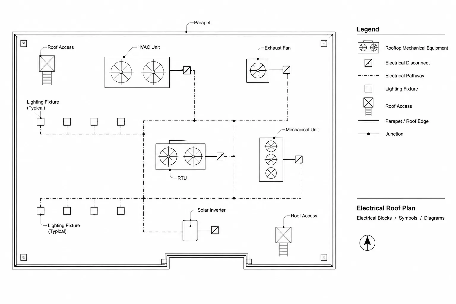
An electrical roof plan documents electrical equipment, connections, pathways, and coordination conditions located at or above a building roof. Although it may cover a relatively small portion of the electrical design, the roof plan often brings several disciplines together in a congested and exposed environment.
A useful roof plan does more than place disconnect symbols beside mechanical equipment. It should help readers understand what is being served, where electrical components are located, how circuits or feeders are referenced, and which items require coordination with architectural, structural, mechanical, plumbing, and lightning-protection information.
This guide focuses on CAD drafting and drawing coordination. Final locations, clearances, ratings, attachment methods, and installation requirements must be verified by the responsible design professionals and project team.
When an Electrical Roof Plan Is Needed
Roof electrical information may be shown on a dedicated electrical roof plan, included on another electrical plan, or divided among power, lighting, and specialty-system sheets. A separate plan is especially helpful when the roof contains multiple pieces of equipment, substantial pathway routing, exterior lighting, photovoltaic equipment, lightning-protection components, or extensive coordination constraints.
Common items shown on an electrical roof plan include:
- Mechanical equipment requiring electrical service
- Local disconnecting devices and control panels
- Receptacles associated with maintenance or equipment areas
- Roof and facade lighting visible from the roof plan
- Raceways, cable tray, or routing diagrams where their locations matter
- Roof penetrations, sleeves, curbs, and pathway entry points
- Photovoltaic modules and associated electrical equipment
- Lightning-protection elements when included in the project documentation
- Communications, security, antenna, or monitoring equipment
- Equipment identification and references to schedules or diagrams
Not every project needs every category. The drawing should show information that communicates design intent and supports coordination without becoming a duplicate of the mechanical or architectural roof plan.
Prepare the Roof Background
Begin with a current architectural roof plan and the relevant mechanical and structural references. Confirm that the CAD background uses the project coordinate system and matches the floor plans below. Roof outlines can differ from the floor below because of setbacks, canopies, penthouses, screen walls, parapets, and lower roof areas.
The background should provide enough context to locate electrical work. Useful reference elements may include:
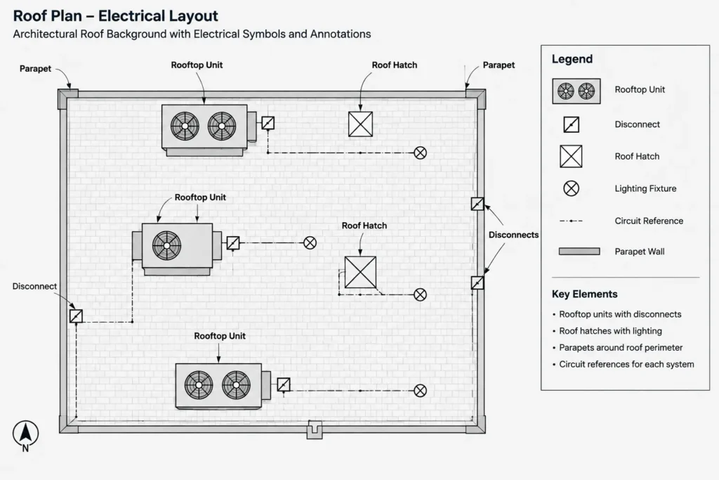
- Roof edges, parapets, and screen walls
- Penthouses and rooftop enclosures
- Mechanical equipment footprints and equipment tags
- Roof access points and designated paths
- Drains, overflow points, and plumbing vents
- Skylights, hatches, and smoke vents
- Expansion joints and structural grid lines
- Roof slope indicators where they affect coordination
- Equipment curbs and major support zones
Use screened or halftoned backgrounds so electrical information remains visually dominant. Avoid tracing architectural or mechanical objects into electrical layers unless there is a specific documentation reason. Referenced backgrounds are generally easier to update and audit than duplicated geometry.
Establish a Clear CAD Layer Structure
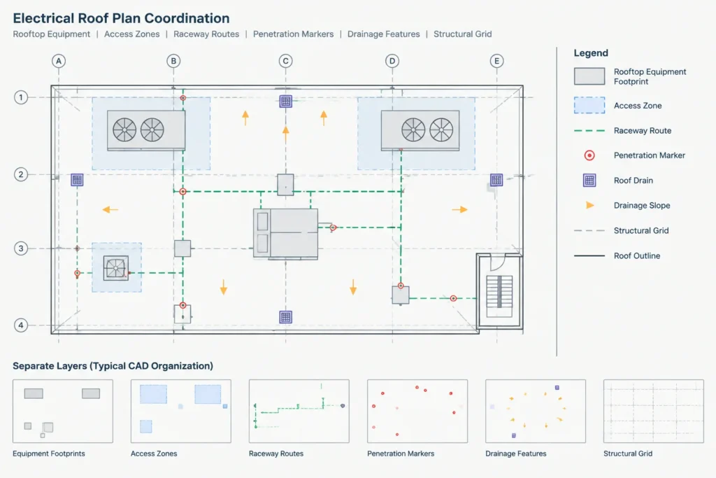
Roof plans benefit from separating objects by function. The exact layer names should follow the project CAD standard, but the layer structure should distinguish electrical design content from reference information.
| Drawing content | Layer purpose | Drafting consideration |
|---|---|---|
| Electrical equipment | Symbols and outlines for electrical components | Keep distinct from mechanical equipment shown in the background |
| Power connections | Circuit graphics, home runs, or connection indicators | Use only where they improve interpretation |
| Raceway or pathway routing | Diagrammatic or coordinated route lines | Identify whether routing is approximate or specifically coordinated |
| Tags and annotations | Equipment IDs, circuit references, and notes | Maintain readable orientation and avoid symbol overlap |
| Lighting | Roof-mounted or exterior luminaires | Coordinate fixture types with the lighting schedule |
| Coordination zones | Clearance, access, or reserved-area graphics | Use restrained linework so zones do not resemble physical equipment |
| Discipline backgrounds | Architectural, structural, and mechanical references | Control display through external-reference settings |
Separate layers also make it possible to produce discipline-specific views without editing the underlying design. For example, a power sheet can suppress lighting information while retaining the same coordinated roof background.
Place Equipment with the Correct Graphic Meaning
A roof plan may show both electrically supplied equipment and standalone electrical components. These should not be represented in the same way. Mechanical units are typically visible as background footprints with their mechanical tags, while electrical devices receive electrical symbols, tags, or connection callouts.
Use symbols that communicate function at the plotted scale. A disconnect symbol should remain recognizable without obscuring the equipment outline. If the plan scale cannot support detailed geometry, use a simplified symbol and reference an elevation, enlarged plan, or typical detail.
Do not assume a downloaded CAD block accurately represents the selected product, enclosure, mounting condition, or access requirements. Treat library blocks as drafting resources. Check their units, insertion point, scale, layer behavior, attributes, and graphic meaning before using them in a project.
Coordinate Equipment Identification
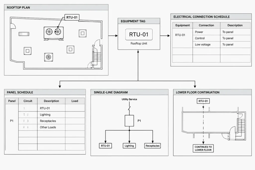
Equipment tags should match the identifiers used by other disciplines. If a rooftop unit is identified on the mechanical drawings, the electrical plan should use that same identifier rather than creating a separate informal name. Electrical equipment such as panels, control cabinets, disconnects, or inverters should likewise remain consistent across plans, schedules, elevations, and diagrams.
A practical tag may connect the roof-plan object to one or more of the following:
- Mechanical equipment schedule
- Electrical equipment connection schedule
- Panel schedule
- Feeder schedule
- Single-line diagram
- Lighting fixture schedule
- Control diagram or detail
Show Power Connections Without Overdrawing
The electrical roof plan should identify the source or circuit relationship clearly, but it does not always need to depict the entire physical route. Circuit tags, home-run graphics, keyed notes, and feeder references can communicate connectivity while keeping the plan readable.
Use linework carefully. A line between a unit and a disconnect may represent a circuit relationship, a raceway route, or merely a graphic leader. The legend, note, or line type should make that meaning unambiguous. Avoid using the same line style for leaders, wiring, pathways, and boundaries.
Where routes are shown, indicate whether they are diagrammatic or coordinated. Diagrammatic routing expresses design intent without fixing every bend or support point. Coordinated routing should reflect known roof obstacles, penetrations, equipment access areas, and interfaces with the structure and roofing system.
Document Roof Penetrations and Transitions
Electrical pathways often transition from an interior electrical room, ceiling space, riser, or exterior wall to rooftop equipment. These transitions deserve deliberate documentation because a simple line ending at a roof unit may not explain how the pathway reaches the roof.
Use penetration markers, riser references, continuation notes, or detail callouts to connect the roof plan with the floor below. Each transition should be traceable across the drawing set. If a penetration is shown on multiple disciplines, coordinate its location and identifier rather than drawing several slightly different versions.
The roof plan can identify the intended location, but construction details may be needed to communicate curbs, sleeves, supports, flashing interfaces, or weatherproofing responsibilities. Electrical drawings should not invent roofing details that belong under another discipline’s design authority.
Coordinate Access and Reserved Areas
Rooftop equipment requires access for operation, inspection, and maintenance. CAD drawings can support this coordination by displaying relevant access paths, door swings, hatches, screen walls, and equipment service zones received from the responsible disciplines.
Use a dedicated layer and a light graphic treatment for clearance or access zones. Add a legend entry so readers understand that the boundary represents a coordination area rather than a constructed curb or enclosure. Overlapping zones should be reviewed, especially near roof edges, mechanical units, photovoltaic arrays, drainage features, and architectural screening.
Do not create arbitrary clearance shapes from visual judgment alone. Obtain required areas from verified project criteria, manufacturer information, and the responsible design team.
Annotate for Field and Drawing-Set Use
Notes should clarify conditions that symbols cannot express. Effective roof-plan annotations may address responsibility boundaries, pathway transitions, coordination requirements, or references to other drawings. They should not repeat obvious graphics or fill the sheet with generic language.
Keep text orientation consistent where practical, and place leaders so they terminate at the intended object rather than crossing unrelated equipment. Use keyed notes for repeated conditions and direct notes for unique conditions. When multiple items are close together, an enlarged plan may be clearer than a dense cluster of leaders.
Coordinate the Roof Plan Across the Set
A roof plan should not be reviewed in isolation. Compare it with the supporting documents before issue:
- Confirm equipment identifiers against mechanical plans and schedules.
- Check electrical loads and connection descriptions against verified design data.
- Confirm circuit and feeder references against panel and feeder schedules.
- Trace major sources and distribution relationships to the single-line diagram.
- Compare pathway transitions with risers and plans on lower levels.
- Check lighting tags against the fixture schedule and control documentation.
- Review penetrations against structural and architectural references.
- Confirm that roof access, drainage, and screening information uses current backgrounds.
When information changes, update every connected representation. A revised equipment tag on the mechanical roof plan may affect an electrical tag, schedule entry, note, detail, and diagram reference.
Roof Plan CAD Quality-Control Checklist
- Verify that the roof background is current and correctly aligned.
- Check that all visible electrical symbols appear in the legend.
- Confirm that blocks use project layers and do not contain unwanted nested layers.
- Review symbol size, text height, and lineweight at the intended plot scale.
- Confirm that tags are unique and consistent across drawings and schedules.
- Distinguish circuit graphics, leaders, and physical pathway routes.
- Check continuation points and references to lower-level plans or risers.
- Review equipment and pathway locations for obvious interdisciplinary conflicts.
- Remove duplicate linework hidden beneath backgrounds or blocks.
- Plot the sheet to verify halftones, masks, hatches, and annotation readability.
Make the Roof Plan a Coordination Drawing
The strongest electrical roof plans explain relationships rather than merely displaying symbols. They identify what equipment is served, connect that equipment to the broader electrical documentation, and reveal where electrical work interacts with roofing, structure, access, drainage, and mechanical systems.
Clear layers, disciplined annotation, coordinated tags, and traceable drawing references make the plan easier to review and maintain. CAD blocks support that process, but they should be treated as editable graphic tools—not substitutes for verified project design information.


Leave a Reply
You must be logged in to post a comment.