
Electrical load summary drawings give reviewers a coordinated view of load data that may otherwise be distributed across calculations, schedules, plans, and diagrams. Their value depends less on visual complexity than on consistent equipment identification, clearly defined load categories, and reliable references to the documents that control the design.
This guide focuses on the CAD and documentation workflow. It explains how to present approved information without changing its engineering basis, connect summary entries to panel schedules and one-lines, and maintain traceability as the drawing set develops.
An electrical load summary drawing presents distribution-system load information in a compact, reviewable format. It does not replace the underlying calculations, panel schedules, or single-line diagram. Instead, it connects those documents by showing where major loads originate, how they are grouped, and which distribution equipment they affect.
A clear summary helps reviewers follow the design without searching through unrelated sheets or calculation pages. It can also reveal documentation conflicts, such as equipment appearing on a floor plan but not in the load calculation, or a panel total that does not match the value carried into the upstream distribution summary.
The drafting task is not to choose calculation methods or engineering assumptions. Those decisions belong to the responsible design professional and must follow project requirements. The CAD task is to organize approved information, preserve its meaning, and make every summarized value traceable to its source.
What an Electrical Load Summary Should Communicate
A useful electrical load summary answers several basic questions:
- Which major distribution boards, switchboards, panels, transformers, or other assemblies are included?
- What load categories contribute to each equipment total?
- Are the displayed values connected loads, adjusted loads, demand loads, or another defined quantity?
- Where can the reader find the supporting panel schedule, equipment schedule, calculation, or diagram?
- How do downstream totals relate to the upstream equipment shown on the single-line diagram?
- Which assumptions, exclusions, alternates, or future loads affect interpretation?
The summary should not force the reader to infer what a number represents. A value labeled only as “total” can be ambiguous. Column headings, notes, and legends should identify the load basis and units used on the project.
Choose the Appropriate Drawing Format
Load information can be presented as a table, a diagram annotation, or a combination of both. The best format depends on the size and complexity of the drawing set.
Tabular summary
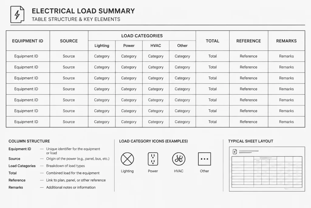
A table is effective when equipment must be compared across common categories. Rows can represent distribution equipment, while columns identify load classifications, summarized totals, references, and remarks. Keep the table structure consistent so readers can scan vertically without interpreting a different arrangement for every row.
Single-line load annotations
Selected load information may be placed beside equipment on the single-line diagram. This makes the relationship between downstream and upstream equipment visually direct, but excessive data can crowd feeders and connection lines. Use this approach for information needed to understand the diagram, and move detailed breakdowns to a separate summary when necessary.
Hybrid presentation
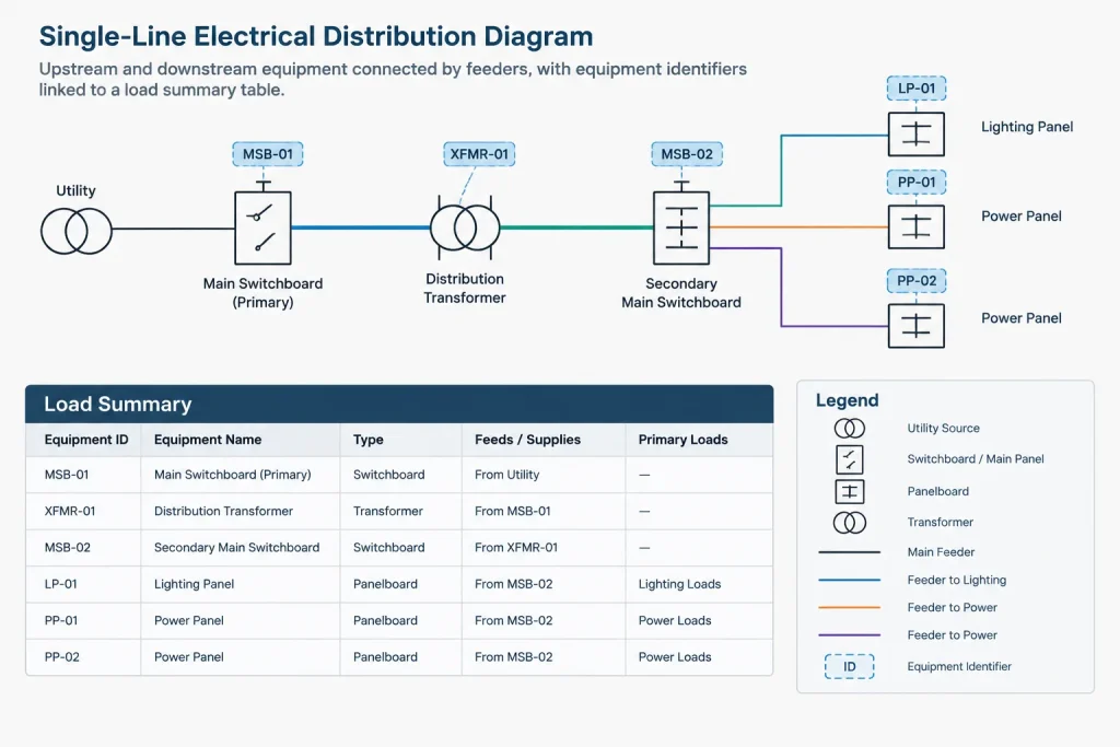
A hybrid format uses concise values on the single-line diagram and a more detailed table elsewhere in the set. Equipment tags serve as the connection between the two. This often provides better readability than repeating a complete calculation beside every diagram symbol.
Build a Traceable Table Structure
The columns in a load summary should reflect the actual project workflow. Avoid adding categories merely because they appeared in an old template. A practical structure may include the following fields:
| Field | Drafting purpose |
|---|---|
| Equipment ID | Matches the identifier used on plans, schedules, and the single-line diagram. |
| Description or area served | Helps distinguish equipment with similar names. |
| Source | Identifies the upstream equipment or documented supply relationship. |
| Load category columns | Separates the project’s approved classifications rather than combining unlike information. |
| Connected load | Records the applicable unadjusted total when that value is part of the design documentation. |
| Adjusted or demand load | Displays the calculated result using the project’s approved method and assumptions. |
| Reference | Points to the supporting schedule, calculation section, diagram, or equipment list. |
| Remarks | Identifies exclusions, future provisions, alternate conditions, or other qualifications. |
Not every project needs every field. The important principle is that headings remain precise and that data can be reconciled with its supporting documentation.
Coordinate Equipment Identifiers Before Entering Values
Equipment identification is the backbone of the summary. Before populating load data, compare the equipment tags on the floor plans, panel schedules, equipment schedules, and single-line diagram.
Look for common naming problems:
- The same identifier assigned to more than one item.
- Different punctuation or spacing used for the same equipment.
- A renamed panel updated on the plan but not in the calculation.
- An equipment tag shown in a schedule but missing from the diagram.
- Temporary design labels that remain after final identifiers are assigned.
Use one controlled identifier as the primary reference. Descriptive text may vary where additional context is useful, but the core tag should remain stable across the set.
Separate Load Categories Without Losing Their Meaning
Load categories should reflect the design calculation and project documentation. Depending on the project, the calculation may distinguish lighting, receptacles, mechanical equipment, process loads, life-safety-related loads, standby loads, or other classifications. The drafter should not reorganize these categories in a way that changes the calculation’s meaning.
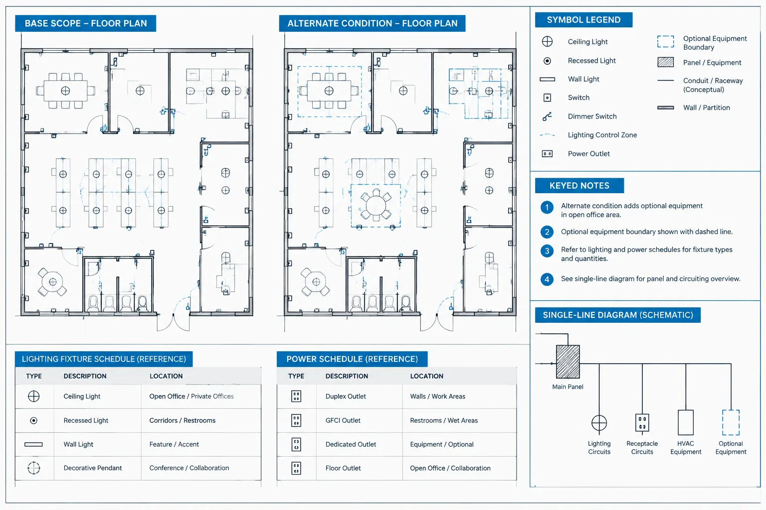
If a category is combined for presentation, make the relationship clear in a note or supporting worksheet. Avoid silently merging data from different operating conditions. Normal operation, alternate operation, and future scenarios may need separate rows, columns, or summary sections so that incompatible conditions are not added together.
Future loads also need unambiguous treatment. Identify whether a value represents an installed load, an allowance, a reserved capacity item, or equipment expected under a later phase. Do not allow graphic conventions alone, such as screened text, to carry this distinction without an accompanying label or legend.
Link the Summary to the Single-Line Diagram
The load summary and single-line diagram should describe the same distribution hierarchy. A useful checking method is to begin with a downstream panel, identify its upstream source, and follow that path through each distribution level. At every step, confirm that the equipment identifiers and summarized values correspond to the supporting documents.
Do not assume that upstream load is simply the visible sum of all downstream table rows. The approved calculation may account for diversity, operating modes, redundant equipment, alternates, or other design assumptions. Where the relationship is not obvious, add a concise reference to the applicable calculation rather than trying to explain the engineering method entirely on the drawing.
Use CAD Formatting That Supports Review
Load-summary graphics should follow the project’s established text, table, layer, and plotting conventions. Keep headings visually stronger than body entries, align comparable data consistently, and provide enough spacing to prevent values from appearing in the wrong column.
Useful CAD practices include:

- Placing table lines, text, notes, and revision graphics on controlled layers.
- Using consistent text styles rather than manually formatted exceptions.
- Keeping equipment IDs visually distinct from descriptive text.
- Avoiding excessive decimal precision copied from working calculations when it is not required for the issued document.
- Testing the table at its intended plotted scale.
- Checking that screened backgrounds or revision clouds do not obscure values.
If the table is generated from linked data, establish who controls the source and how updates are refreshed. If it is manually maintained, use a documented comparison process so that changes in calculations and schedules reach the CAD sheet.
Manage Revisions Without Breaking Traceability
A load change can affect several documents at once. When equipment is added, removed, or reassigned, review the floor plan, equipment connection information, panel schedule, load calculation, distribution summary, and single-line diagram as a coordinated group.
Revision notes should describe the documented change rather than simply stating that the table was updated. During design development, a temporary change log can record the equipment ID, source document, affected sheets, responsible reviewer, and update status. This working log does not have to appear in the issued set, but it helps prevent partial updates.
Quality-Control Checklist
Before issuing an electrical load summary drawing, verify the following:
- Every equipment ID matches the plans, schedules, and diagrams.
- Column headings define the type of load being shown.
- Units are stated and applied consistently.
- Totals match the current approved calculation source.
- Future, spare, alternate, and excluded loads are clearly identified.
- Operating scenarios are not combined without explanation.
- Upstream and downstream relationships agree with the single-line diagram.
- Supporting references point to current documents.
- Obsolete rows, duplicated equipment, and placeholder values have been removed.
- The final plotted table is legible and no text is clipped or masked.
Make the Summary a Navigation Tool
The strongest electrical load summary is more than a collection of totals. It acts as an index to the distribution design. Equipment IDs connect it to plans and diagrams, category headings connect it to the calculation, and references guide the reader to supporting detail.
By treating traceability as a drafting requirement, CAD teams can produce summaries that are easier to review and less likely to become disconnected from the rest of the drawing set. The result is not a substitute for engineering analysis, but a clearer and more dependable presentation of that analysis.
Define the Controlling Source for Each Entry
A coordinated summary needs a clear source hierarchy. The calculation package may control calculated load values, while panel schedules, equipment schedules, and the single-line diagram control other parts of the documentation. The project team should identify which document governs each field rather than treating the CAD table as an independent source.
When two documents disagree, copying the most recent-looking value into the summary can hide the conflict. Flag the discrepancy for resolution, record the document from which the approved value was obtained, and update connected drawings only after the responsible team confirms the change.
Distinguish source data from presentation data
Source data includes approved equipment identifiers, load classifications, calculated results, supply relationships, and operating assumptions. Presentation data includes column order, text alignment, note placement, linework, and sheet organization. Drafters may refine presentation without altering the meaning of the source data.
Use Status Controls During Design Development
Load information may pass through preliminary, coordinated, reviewed, and issued states. A working summary should make incomplete entries visible to the project team without allowing temporary content to appear final. Placeholder text, unresolved references, and provisional equipment tags should be tracked through the project’s established review process and removed or resolved before issue.
Revision clouds alone do not establish data status. A cloud shows where a drawing changed, but it does not explain whether the supporting calculation, panel schedule, and one-line were reviewed together. A separate coordination record can help the team confirm that each affected document moved through the same review cycle.
Plan for Data Exchange Without Losing Accountability
A load summary may be entered manually, imported from a worksheet, or generated from a coordinated design database. Automation can reduce repeated entry, but it does not remove the need for review. Imported fields should retain recognizable equipment identifiers, category definitions, and source references so reviewers can compare the output with the approved documentation.
Before refreshing linked information, confirm whether local CAD edits will be overwritten. After refreshing it, inspect the plotted result as well as the underlying data. A technically correct import can still create clipped notes, displaced columns, hidden entries, or an unreadable table.
Support the Review Path
A reviewer should be able to select an equipment row, find the corresponding schedule or diagram item, identify its upstream source, and locate the supporting calculation reference without relying on undocumented naming conventions. If that path breaks, the issue is usually a coordination problem rather than a graphic problem.
Keeping that review path intact makes the load summary useful throughout design development, quality control, and later drawing revisions. It also helps prevent the summary from becoming an isolated table that appears complete but no longer agrees with the documents behind it.
Frequently Asked Questions
Is an electrical load summary the same as a load calculation?
No. The summary presents selected approved results and references in a drawing-friendly format. The calculation contains the engineering methods, assumptions, and supporting analysis.
Should every panel schedule value appear in the summary?
Not necessarily. The included information should match the purpose and scope of the drawing set. Detailed circuit data can remain in panel schedules while the summary presents the equipment-level information needed for coordination.
Can load data be shown directly on a single-line diagram?
Yes, when the annotations remain clear and support understanding of the distribution system. A separate table is often easier to review when detailed categories or qualifications would crowd the diagram.
What should happen when the summary and panel schedule disagree?
The difference should be treated as a coordination issue and referred to the responsible project team. The drafter should not select or recalculate a value without confirmation of the controlling source.
How should future or alternate loads be documented?
They should be explicitly labeled and kept distinct from installed or active design conditions. Notes, headings, or separate summary areas should explain their status rather than relying only on color, screening, or line type.
Who is responsible for calculation assumptions?
The responsible design professional establishes and approves calculation methods and assumptions. The CAD team organizes that approved information and keeps its references consistent across the drawing set.


Leave a Reply
You must be logged in to post a comment.