Electrical CAD layer naming is more than a file-management preference. A well-organized layer structure helps designers, drafters, reviewers, and coordinators understand what a drawing contains, control visual emphasis, and make revisions without disturbing unrelated information. A poorly organized file can still look acceptable on screen, yet become difficult to edit, print, coordinate, or hand over.
This guide explains a practical way to plan electrical CAD layers for floor plans, reflected ceiling plans, equipment layouts, single-line diagrams, and related drawing views. It does not prescribe one universal naming system. Project teams should follow their established CAD standards, title-block conventions, and document-control procedures when those are available.
What an electrical CAD layer does
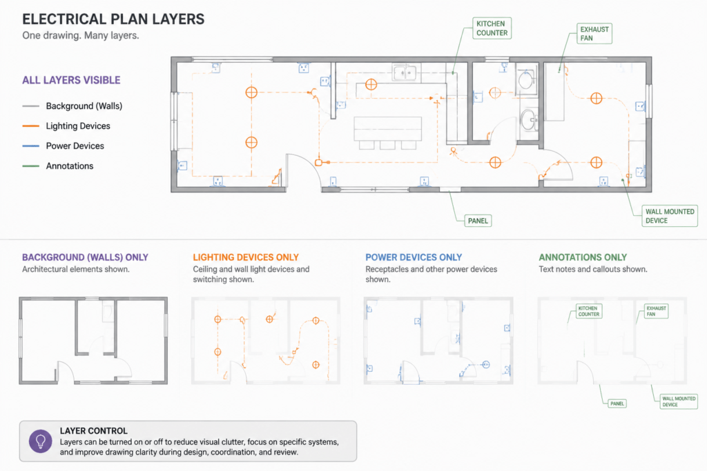
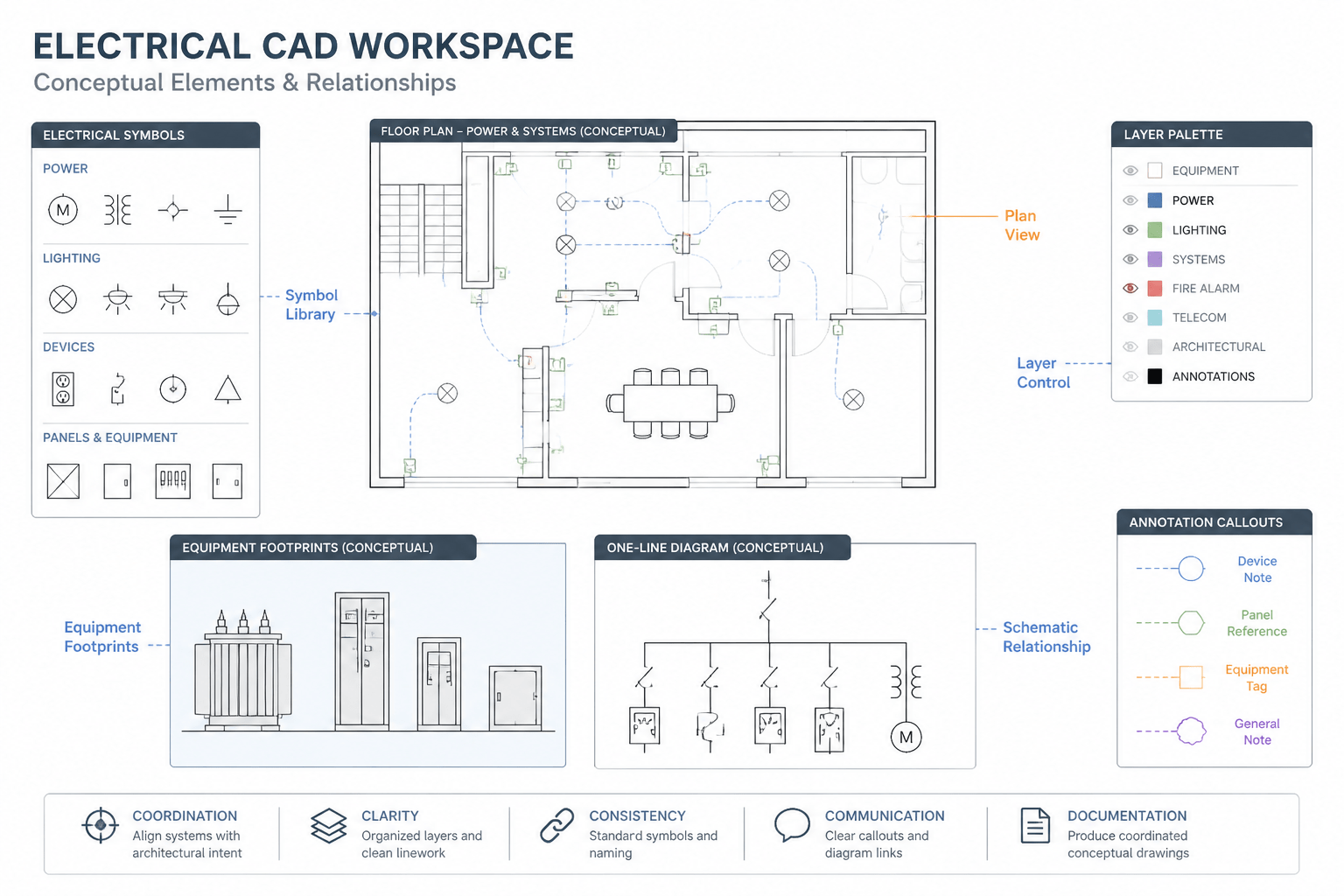
A layer is a logical container for drawing objects. It can group geometry by discipline, system, drawing purpose, or graphic treatment. Layer controls commonly affect visibility, color, lineweight, linetype, plotting behavior, and whether an object can be edited.
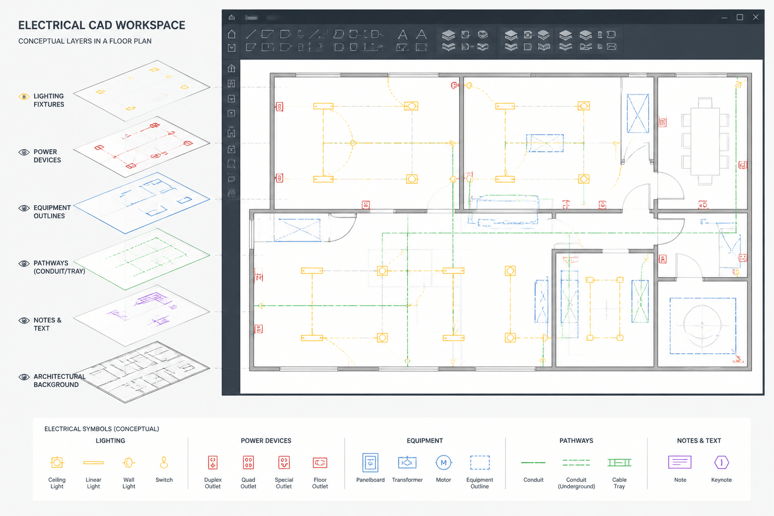
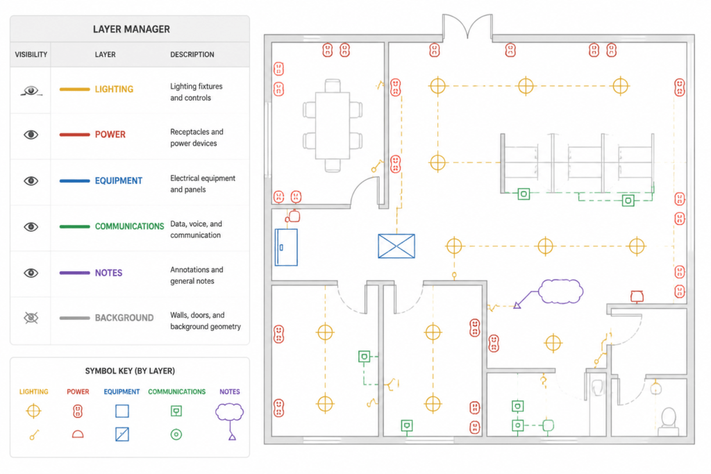
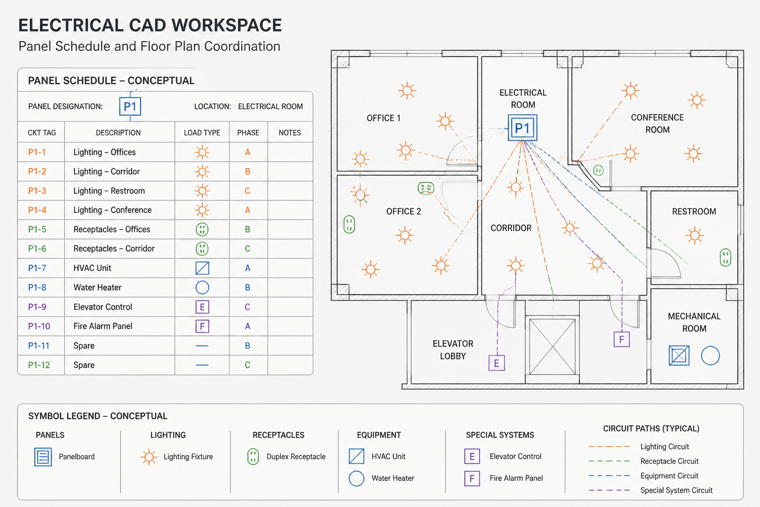
For electrical work, layers often separate items such as lighting fixtures, receptacles, equipment, circuiting, home runs, communication devices, notes, and architectural backgrounds. The exact categories depend on the project and the level of information shown.
The important principle is to assign a layer according to the object’s meaning, not simply according to when it was drawn. For example, a receptacle symbol should remain on a power-device layer even if it appears on a general floor plan. This makes the object easier to isolate and revise later.
Start with a layer strategy, not a layer list
Before creating layers, decide what the drawing needs to communicate. A small tenant-improvement plan may need only a few electrical categories. A larger project may require separate layers for normal power, emergency-related information, lighting controls, fire alarm, data, security, and equipment connections. Creating every possible category in advance can make the file harder to navigate.
A useful strategy answers four questions:
- What system does the object represent? Examples include lighting, power, communications, fire alarm, or grounding.
- What kind of information is it? It may be a device, cable path, circuit annotation, equipment outline, note, or reference symbol.
- Where will it be used? A plan-view device and a schematic symbol may need different graphic treatment even when they describe related equipment.
- Should it plot? Construction information, coordination backgrounds, working references, and non-plotting guides should not be mixed without a clear reason.
This approach produces a manageable structure and avoids names that are too broad, such as “ELECTRICAL,” which force users to select individual objects manually.
A practical naming pattern
Layer names work best when their parts follow a consistent order. One possible pattern is:
Discipline – System – Object or Information Type – Status or Use
For example, a team might distinguish electrical power devices from lighting devices, then separate each from notes or circuiting. The exact abbreviations are less important than consistency and readability.
Keep names predictable. If one layer uses “LIGHTING” while another uses “LTG,” users must remember two vocabularies. Decide whether the project will use full words, approved abbreviations, or a combination. Then document those choices in a layer key or CAD setup guide.
Avoid names that depend on a temporary view, drafter, or sheet number. Objects can move between sheets and viewports during coordination. A layer should describe the object or information, not its current location in the drawing set.
Common electrical layer groups
The following groups are useful starting points for many electrical drawing environments. They are categories to consider, not a universal required list.
| Layer group | Typical content | Coordination purpose |
|---|---|---|
| Lighting | Fixtures, switching devices, control relationships, and lighting notes | Separates lighting information from power and background geometry |
| Power | Receptacles, small power devices, circuit indications, and related annotations | Allows power layouts to be reviewed independently |
| Equipment | Electrical equipment outlines, connection points, and identification tags | Supports equipment coordination with architectural and mechanical layouts |
| Distribution | Panel, transformer, switchboard, or distribution references shown in the relevant view | Helps distinguish distribution information from branch devices |
| Communications | Data, telephone, audiovisual, or other low-voltage device graphics | Reduces confusion between power and signal-related layouts |
| Pathways | Conduit, cable tray, raceway, or routing information when shown | Provides a dedicated visibility control for physical pathways |
| Notes and tags | General notes, keynotes, labels, and circuit identifiers | Allows annotations to be reviewed or adjusted separately |
| Backgrounds | Architectural walls, doors, ceilings, grids, and reference geometry | Controls the visual prominence of non-electrical information |
Some teams separate objects and annotations into different layers; others keep them together by system. Either method can work if it remains predictable and supports the project’s review process.
Use color and lineweight as visual controls
Layer colors are useful during drafting, but screen color should not be treated as the sole meaning of an electrical symbol. A user may change the display mode, use a monochrome plot style, or open the drawing with a different color setup. The layer name, symbol shape, and annotation should still communicate the object’s purpose.
Lineweight should establish hierarchy. Primary electrical equipment, major pathways, and important outlines may need stronger visual emphasis than secondary references or background walls. Small devices and notes need enough contrast to remain legible without overpowering the plan.
When a drawing is intended for plotting, test the result rather than judging only the model-space display. Check whether dashed pathways remain distinguishable, whether notes are readable at the intended sheet scale, and whether adjacent systems can be separated visually.
Separate model information from sheet presentation
Many CAD workflows use model space for drawing information and paper space or sheet layouts for presentation. Layer planning should account for both. A layer may be visible in one viewport and hidden in another, allowing a common model to support different plan views.
Do not create unnecessary duplicate geometry simply because one sheet needs a different display. Viewport controls, carefully managed annotation, and reference layers may provide a cleaner solution. At the same time, avoid hiding information in a way that makes the drawing difficult for another user to understand. A clear layer key and consistent viewport setup are essential.
Blocks, attributes, and layer behavior
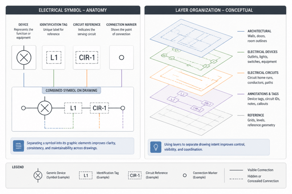
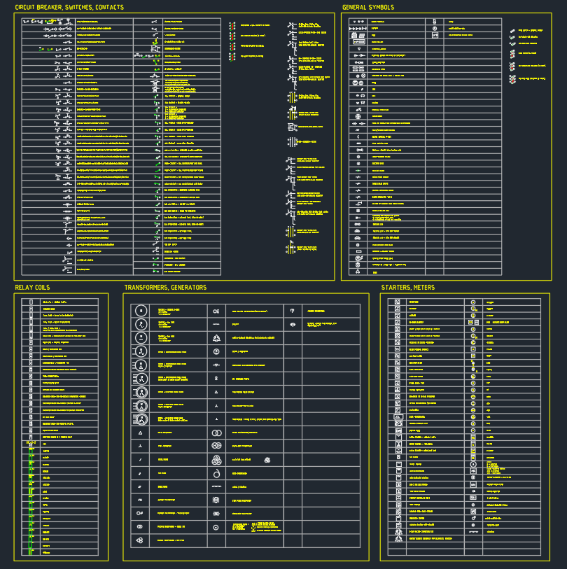
Electrical symbols and equipment blocks should be built with layer behavior in mind. A block’s internal geometry can either follow the layer of the inserted reference or retain its own assigned layers. The chosen approach affects visibility control and editing.
For example, a device block may contain several graphic elements: the symbol, an identification attribute, a circuit reference, and a connection marker. If these elements are all placed on unrelated layers, turning off one category may leave confusing fragments behind. If everything is placed on one broad layer, users lose useful control.
Before using a block library, test how its attributes display, plot, and respond to layer changes. A block that looks correct in one drawing can behave unexpectedly when inserted into a coordinated project file.
Layer practices for different drawing types
Electrical floor plans
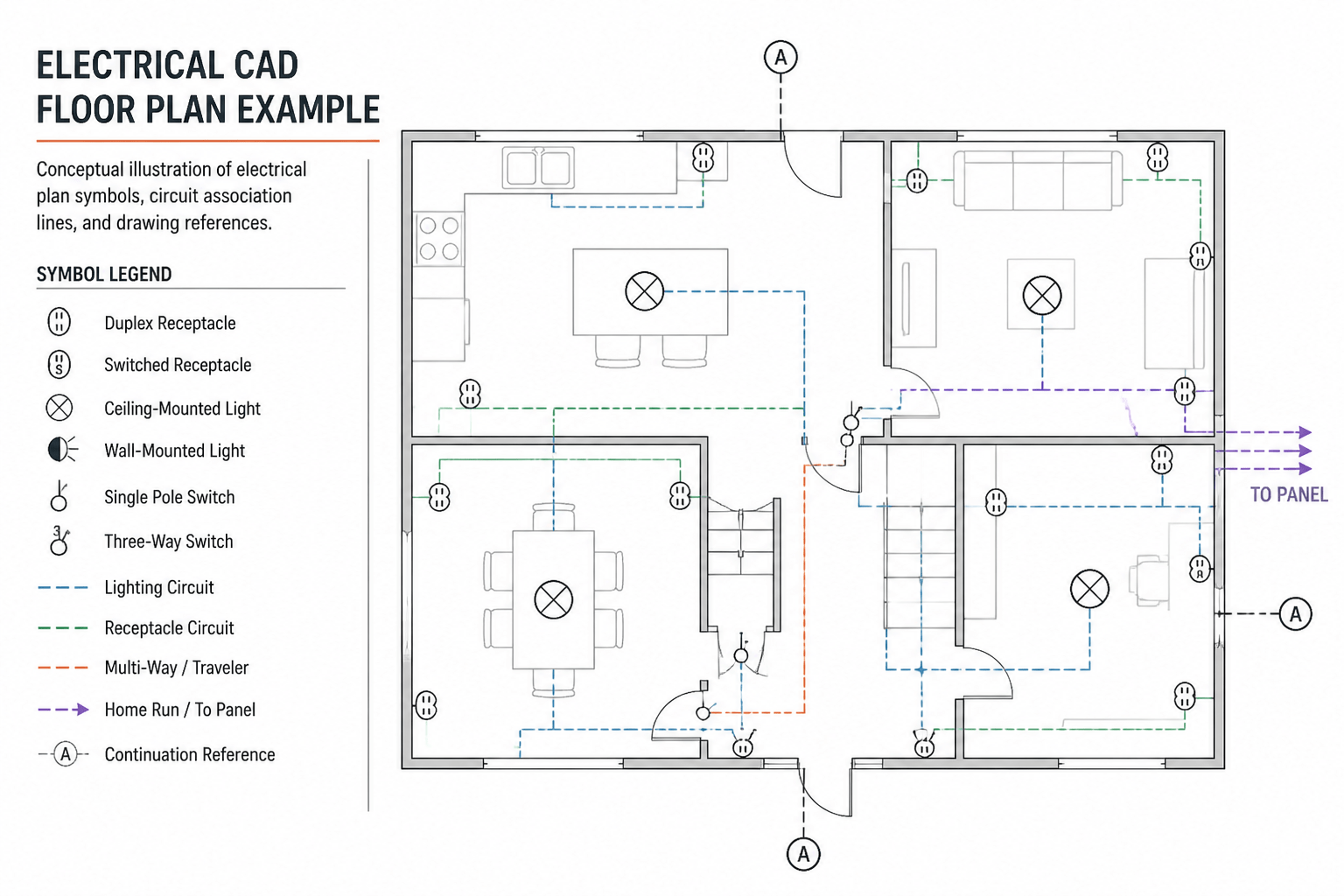
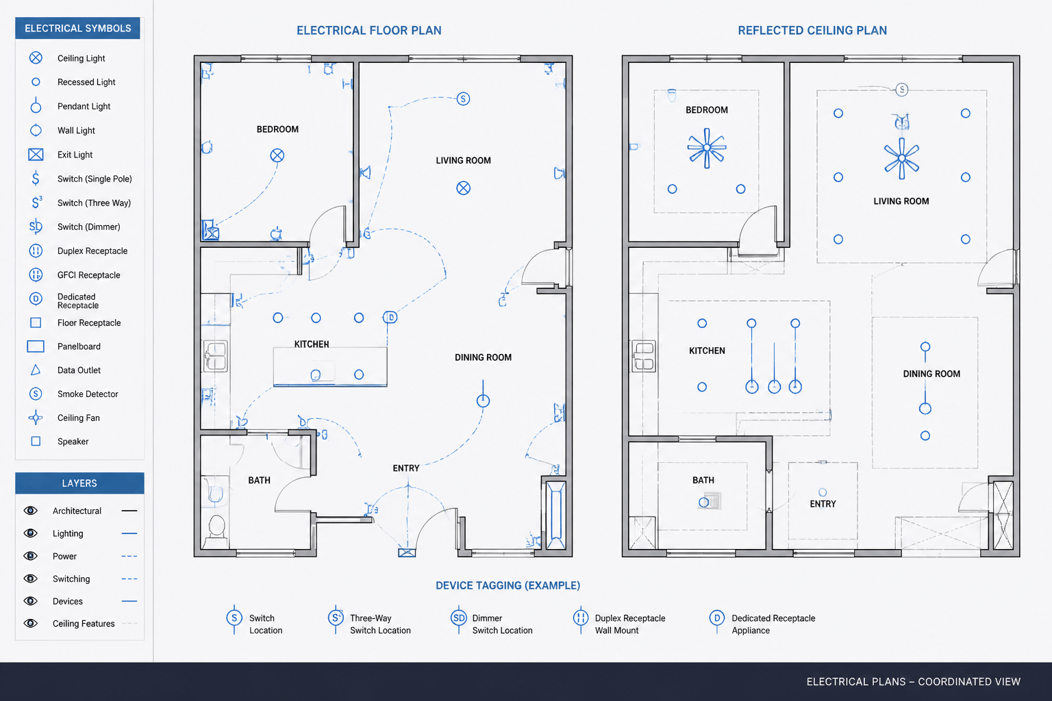
Floor plans usually benefit from clear separation between devices, circuiting, equipment, notes, and backgrounds. Keep architectural references visually subordinate so electrical information remains easy to follow.
Reflected ceiling plans
Lighting layouts often require a different emphasis from floor-mounted power devices. Ceiling grids, fixture graphics, switching information, and control annotations should be easy to distinguish without relying only on color.
Single-line and schematic diagrams
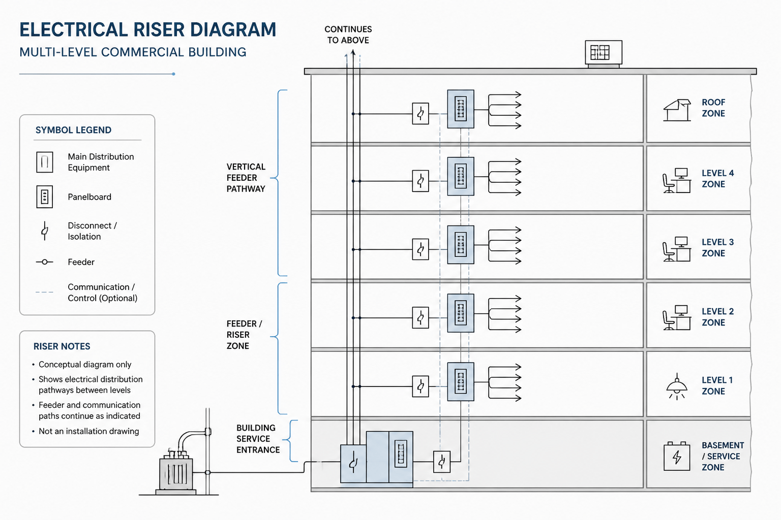
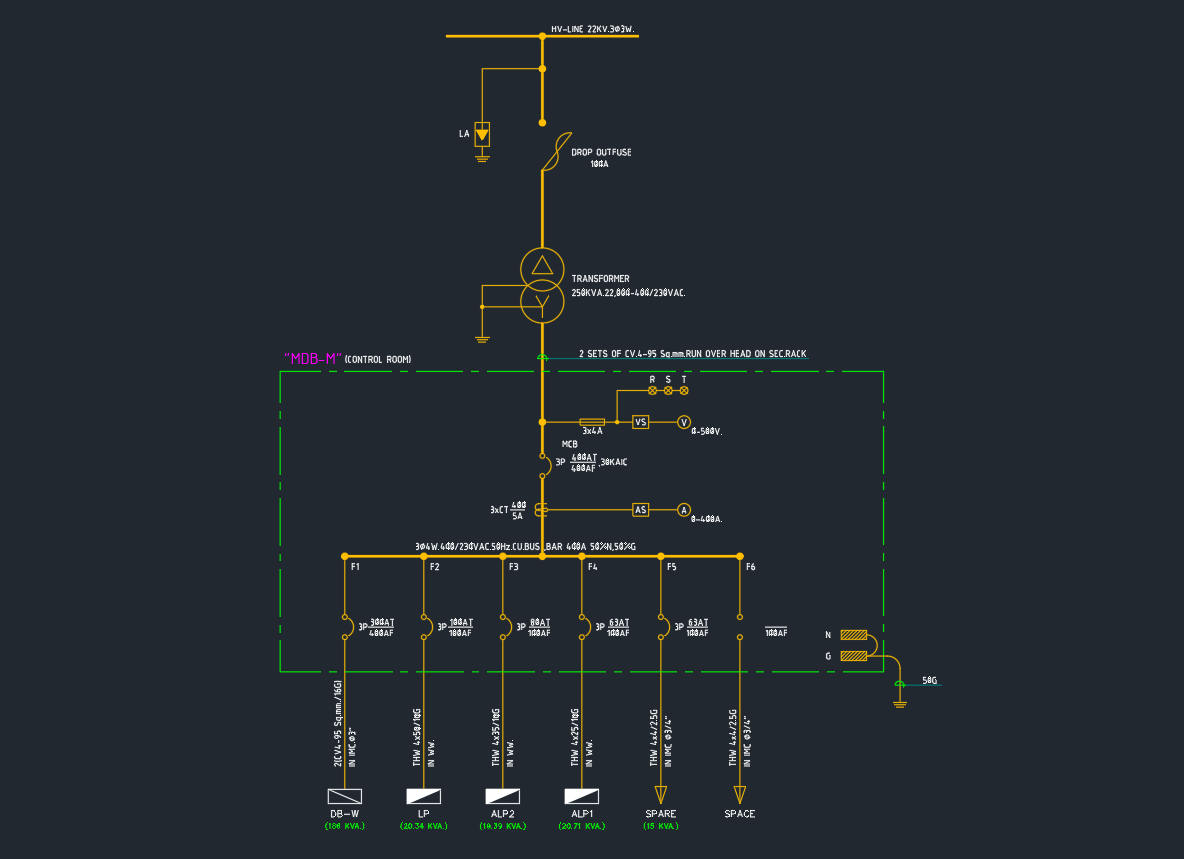
Diagram layers may be organized around equipment symbols, conductors or connections, labels, protective-device references, and notes. Because diagrams are not scaled floor plans, layer organization should prioritize logical relationships and editing clarity rather than physical location.
Equipment layouts
Equipment drawings often need separate treatment for outlines, clearances or coordination references, connection points, tags, and background geometry. Do not imply that a conceptual CAD block represents a verified installation arrangement.
Review and maintain the layer system
A layer structure should be reviewed as the drawing develops. Remove unused layers when appropriate, identify duplicate names, and check for objects placed on the default layer or on a generic catch-all layer. Purging unused definitions can help, but it should be done carefully because blocks, external references, and templates may depend on them.
Include a concise layer key when other people will edit or review the file. The key can explain abbreviations, plotting intent, and special visibility controls. A good layer system is not merely tidy; it helps a new user understand the drawing without reverse-engineering the file.
Final checklist
- Does each layer describe a clear system, object type, or drawing function?
- Are abbreviations consistent across the file and related drawings?
- Can lighting, power, communications, equipment, and backgrounds be isolated when needed?
- Do colors, lineweights, and linetypes remain understandable when plotted?
- Have blocks and attributes been tested for predictable layer behavior?
- Are notes, tags, and reference geometry controlled without hiding essential information?
- Does the layer key explain project-specific choices?
Good electrical CAD layer naming makes a drawing easier to read, coordinate, revise, and reuse. The best system is not the one with the most layers. It is the one that gives users enough control to understand the electrical information while keeping the file simple enough to maintain.
Leave a Reply
You must be logged in to post a comment.