
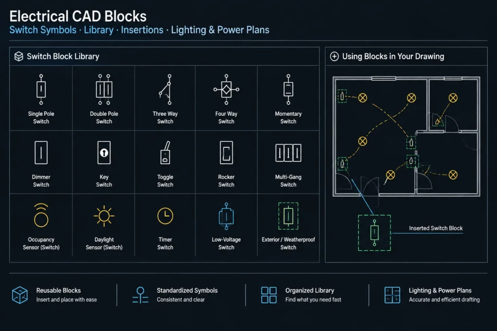
Switch symbols help communicate control intent across electrical plans, schematic diagrams, and building layouts. This page provides a downloadable DWG collection for drafters who need reusable switch graphics in an AutoCAD-based documentation workflow.
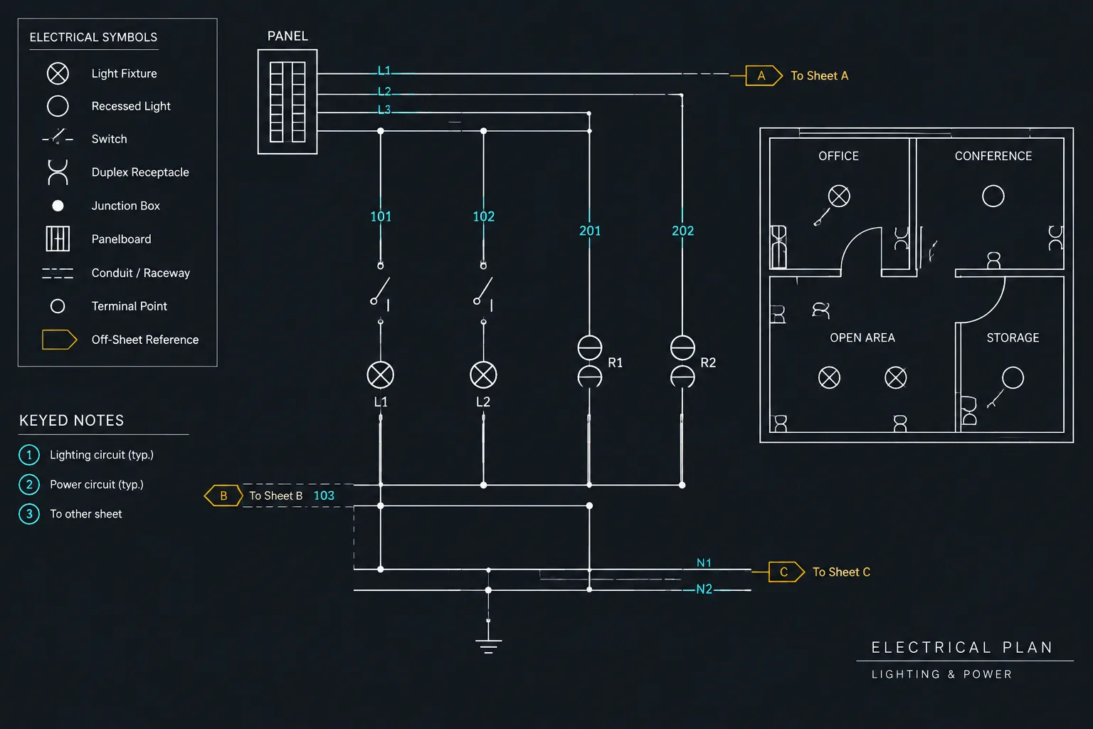
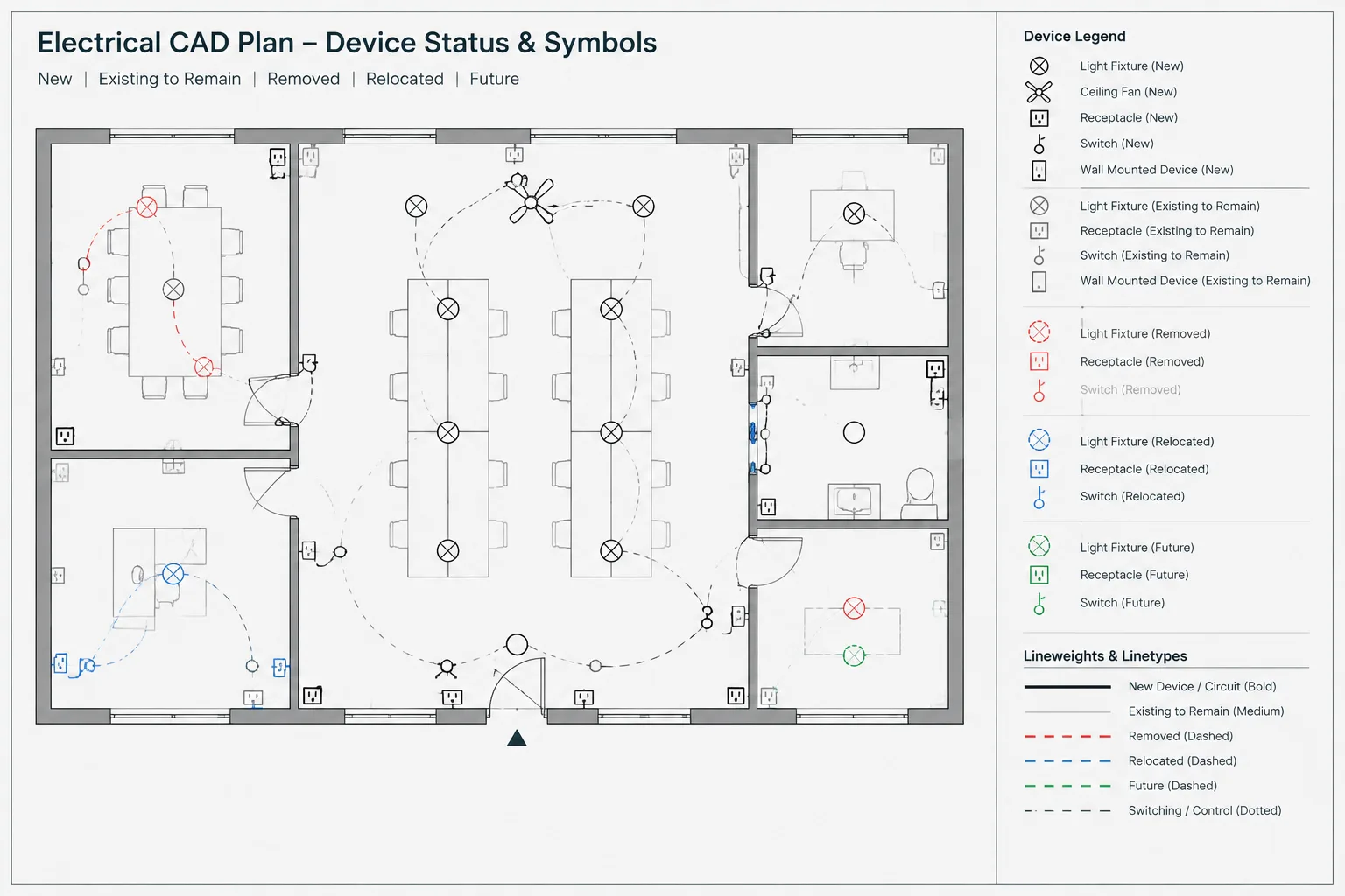
Before placing any block, compare its appearance with the project legend and drawing conventions. Switch graphics can vary by drawing type, office standard, client requirement, and intended level of detail. A symbol that works on a floor plan may not be the preferred representation for a circuit diagram.
Download a high-quality DWG file featuring a comprehensive collection of Switches Symbols CAD blocks, perfect for your electrical design projects. This CAD block set includes various standard switch symbols used in architectural and engineering drawings, ensuring precise and professional documentation. Ideal for electrical plans, circuit diagrams, and building layouts, these symbols streamline your workflow in AutoCAD and other compatible CAD software. Enhance your schematic designs with these ready-to-use Switches Symbols, saving time and ensuring industry-standard accuracy in every project. Compatible with all recent AutoCAD versions for seamless integration.
Please log in or register to download this file.
Using Switch Symbols in CAD Drawings
A switch block is most useful when its graphic, layer assignment, annotation, and meaning remain consistent throughout the drawing set. Insert the required symbol into a working file, confirm its intended meaning, and adapt its presentation to the established CAD standard without obscuring the original design intent.
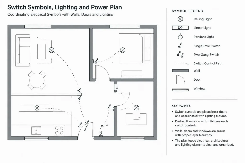
Review the Symbol Before Placement
- Meaning: Confirm what each graphic represents by checking the project legend or symbol schedule.
- Drawing context: Determine whether the symbol belongs in a lighting plan, power plan, control diagram, schematic, or equipment layout.
- Layer: Place the block on the appropriate electrical layer so visibility, color, lineweight, and plotting behavior can be managed consistently.
- Orientation: Rotate or mirror a symbol only when doing so preserves its documented meaning and readability.
- Annotation: Coordinate tags, notes, circuit references, and control identifiers with the rest of the plan.
- Plot review: Check that the symbol remains distinguishable at the sheet’s intended plotting scale.
Block Management and Drawing Consistency
Keep an approved working copy in the project’s symbol library rather than repeatedly importing unrelated versions. Consistent block names make it easier to locate, replace, count, and audit symbols. If attributes are added for tags or descriptions, use a predictable naming method that supports schedules and drawing reviews.
Avoid exploding blocks unless the documentation workflow requires editable geometry. Retaining the block definition generally makes global corrections and symbol replacement easier. When duplicate definitions exist, review them carefully before redefining a block, because an update may affect every matching instance in the drawing.
Related Electrical Drawing Context
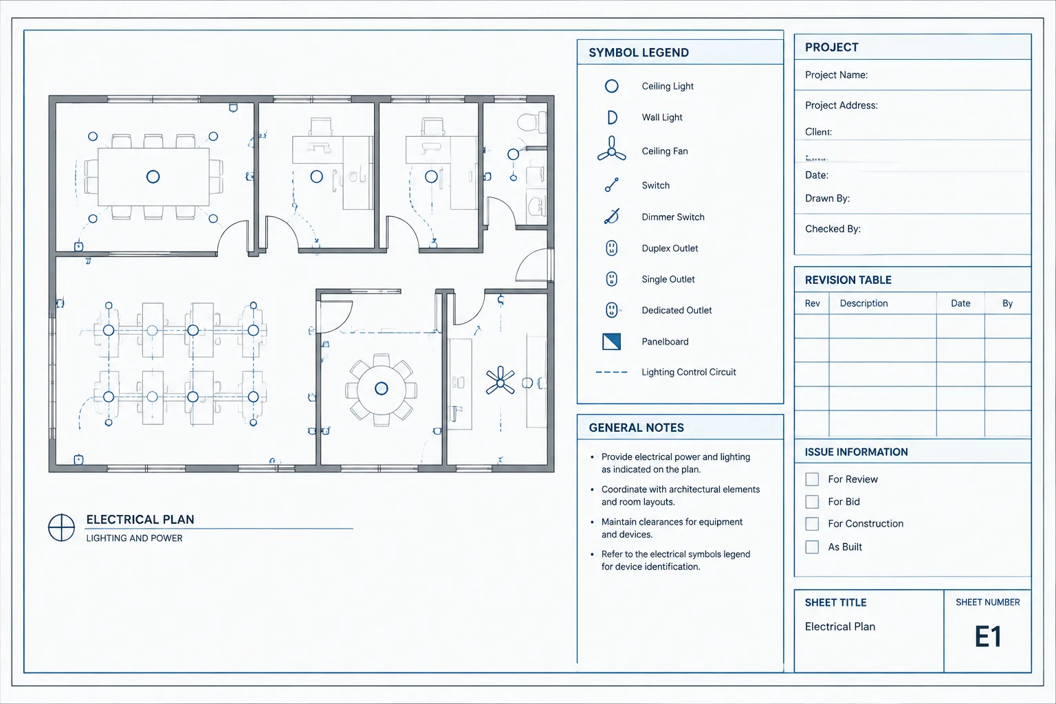
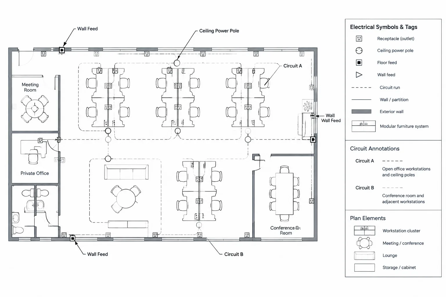
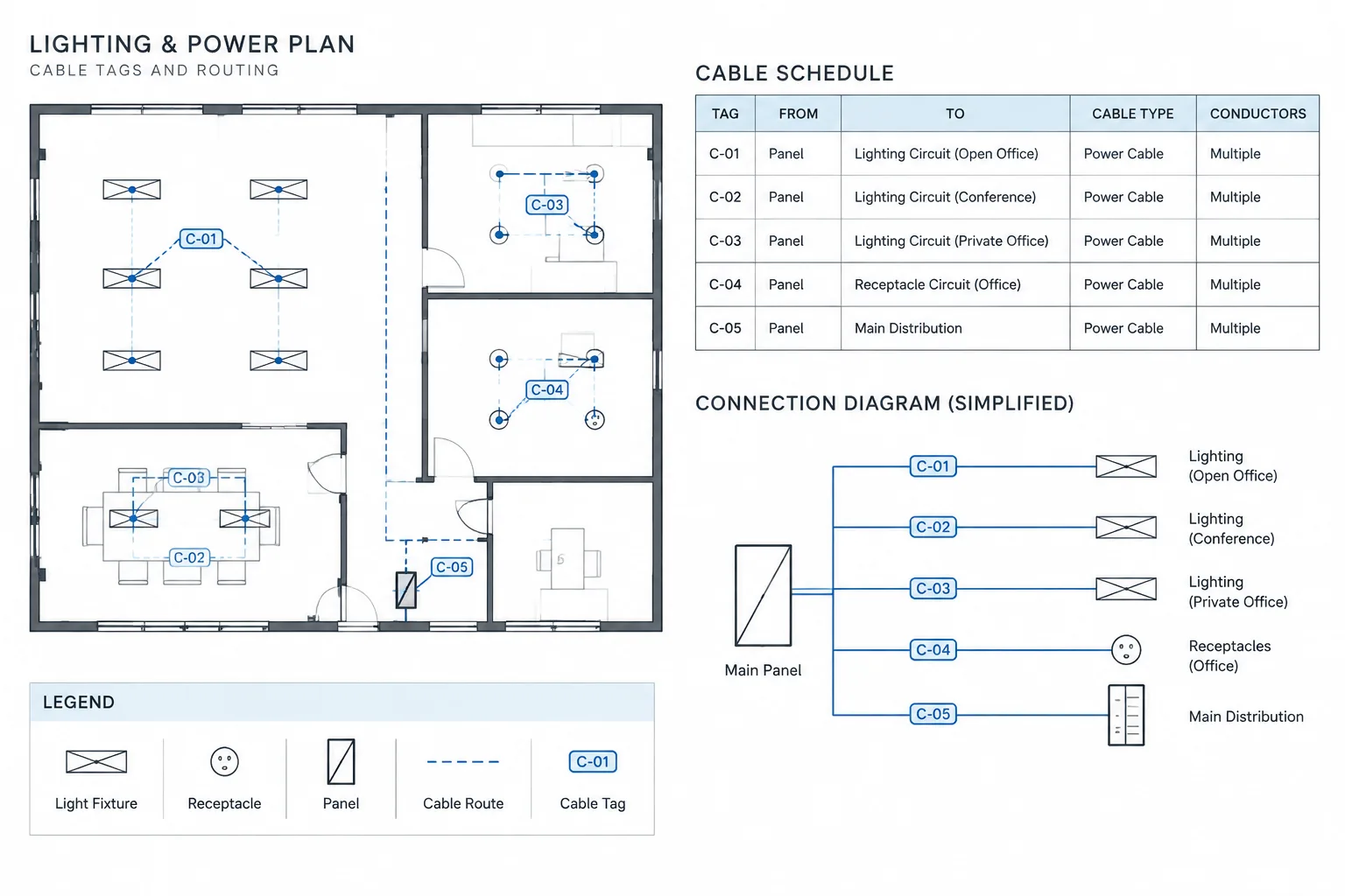
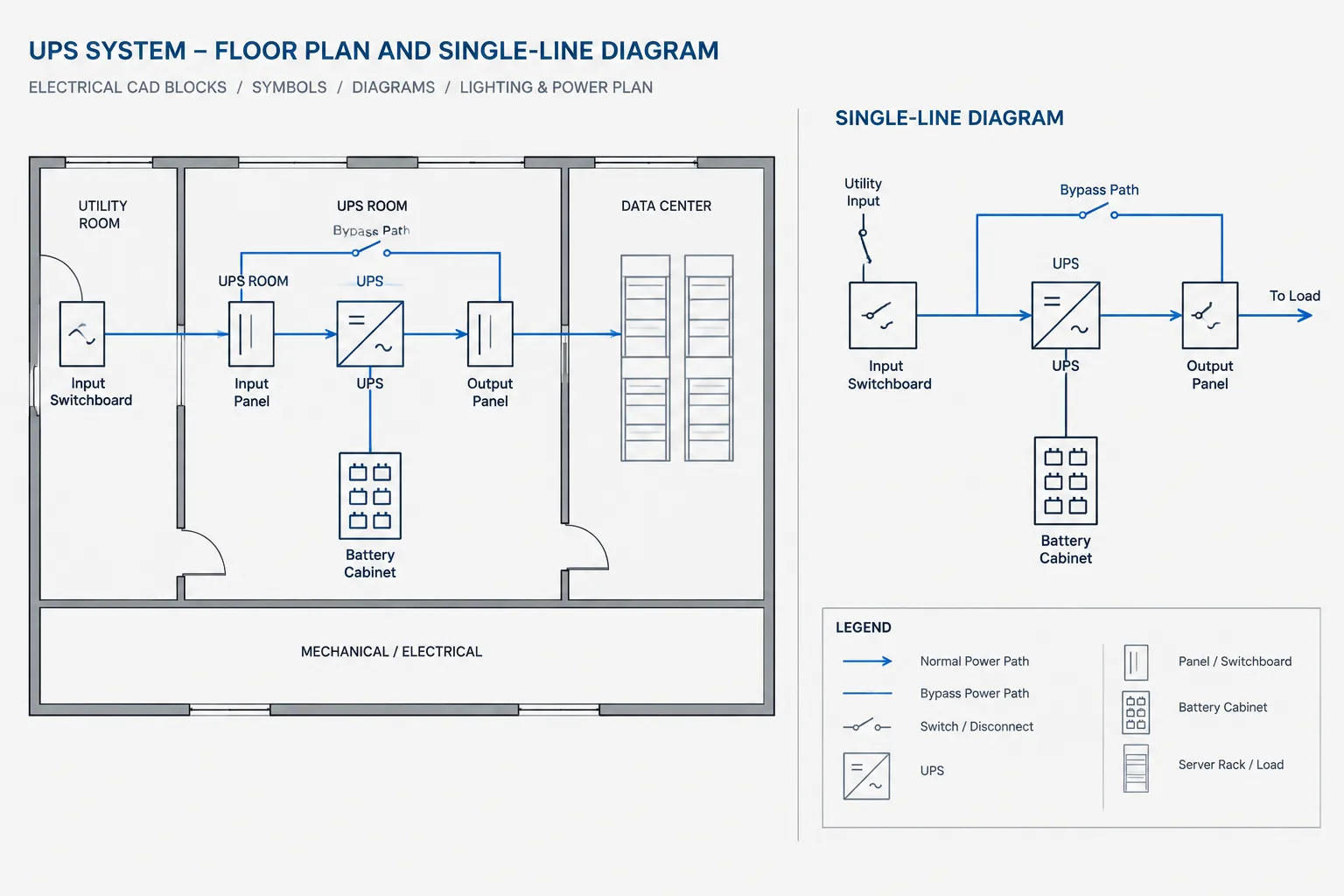
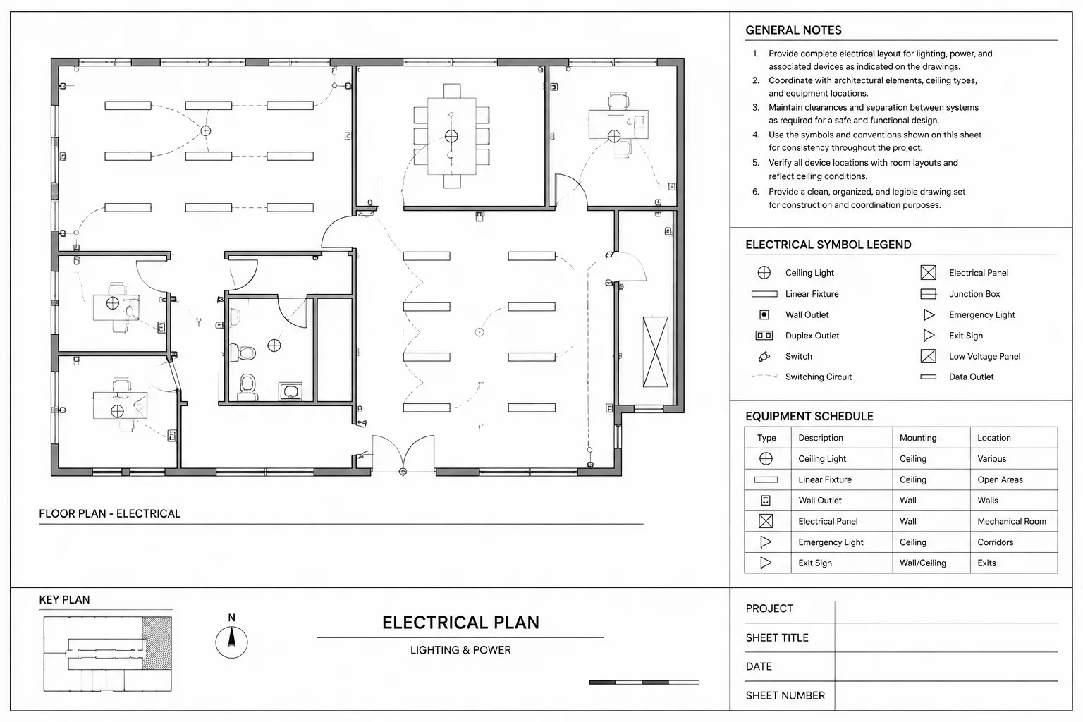
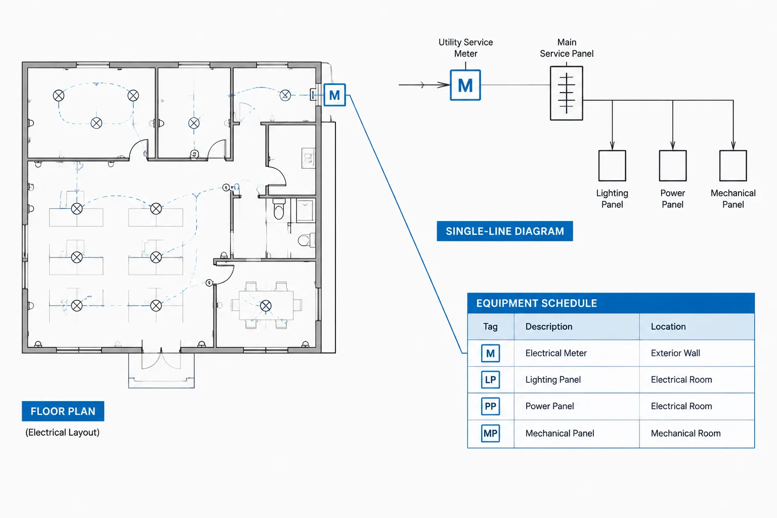
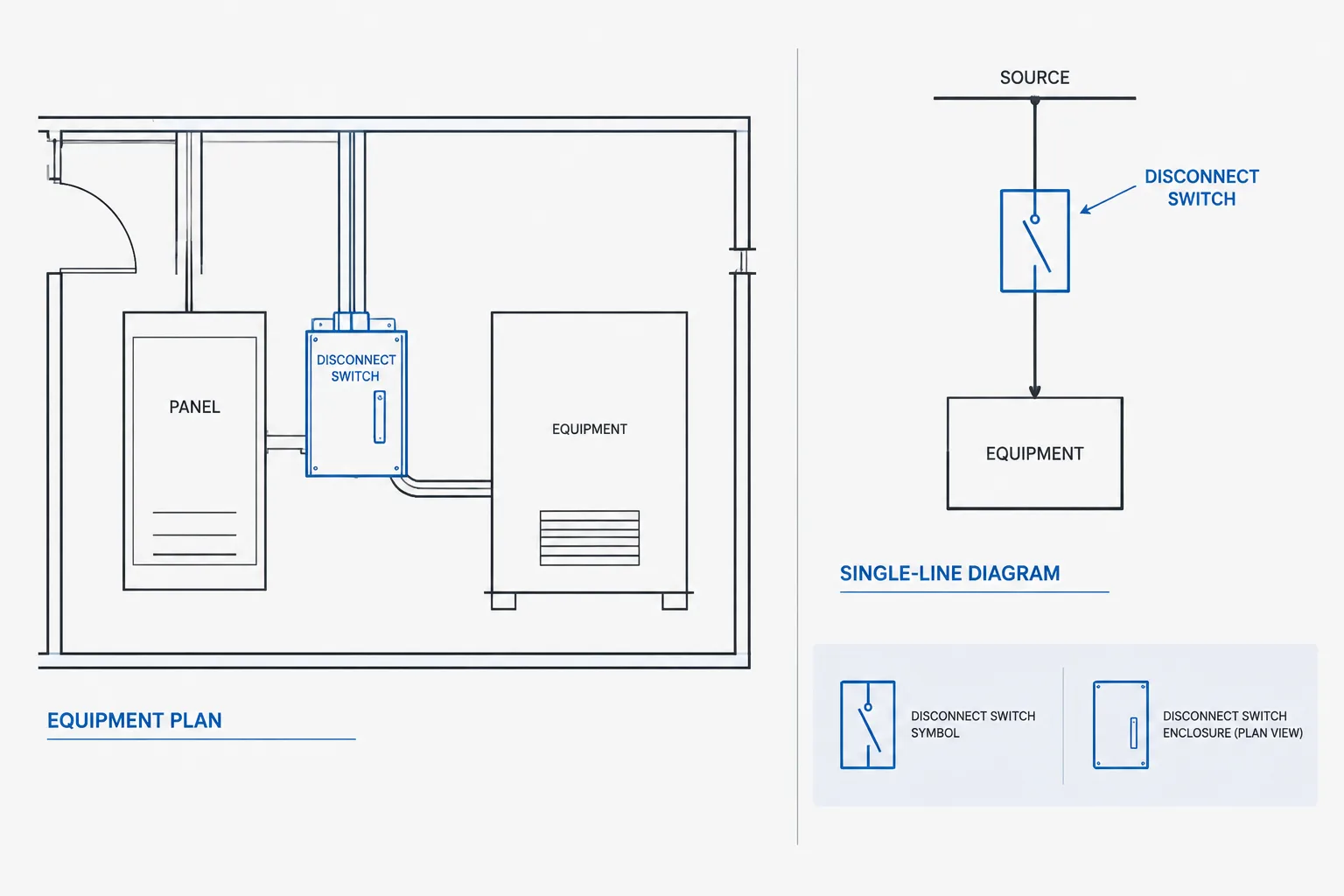
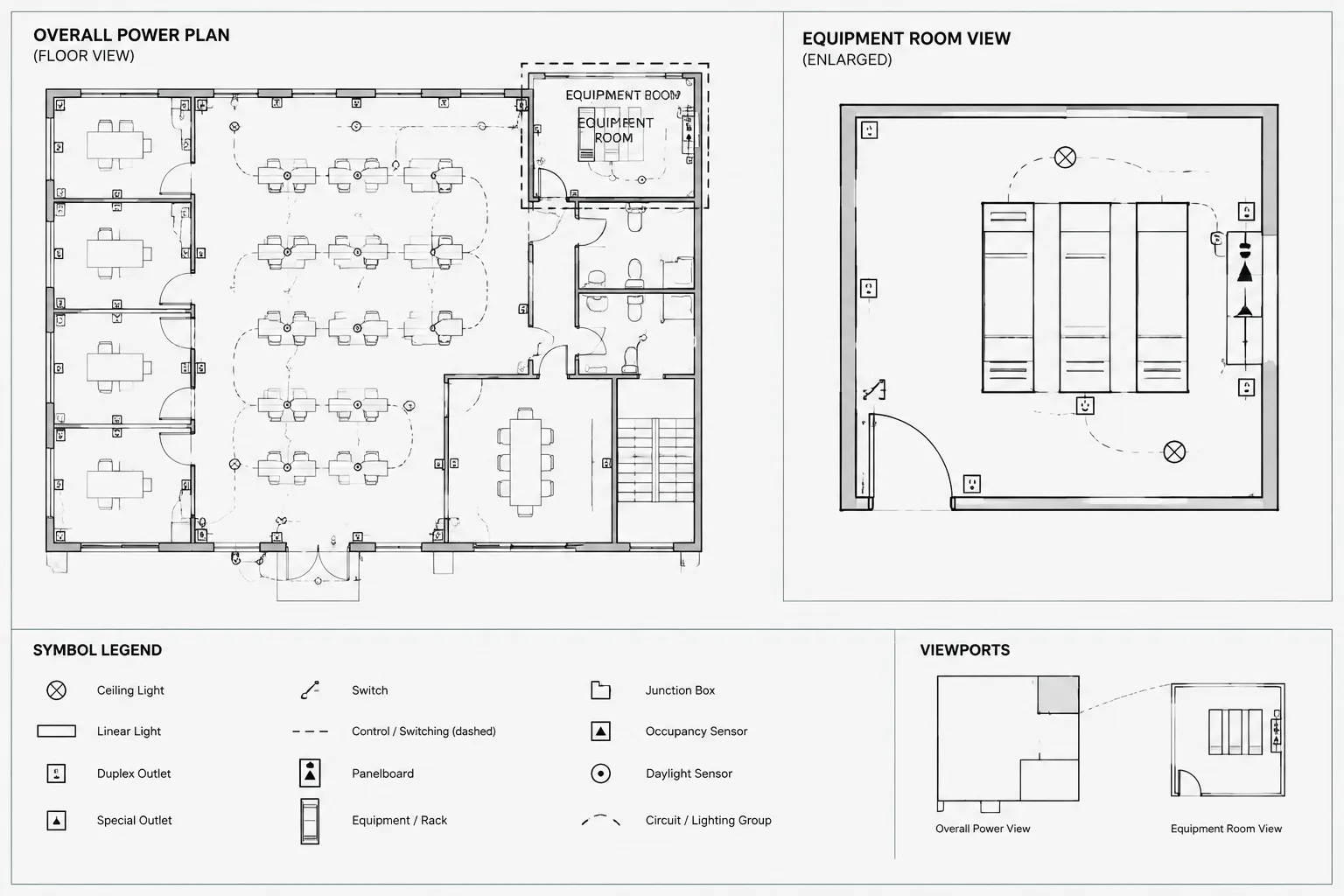
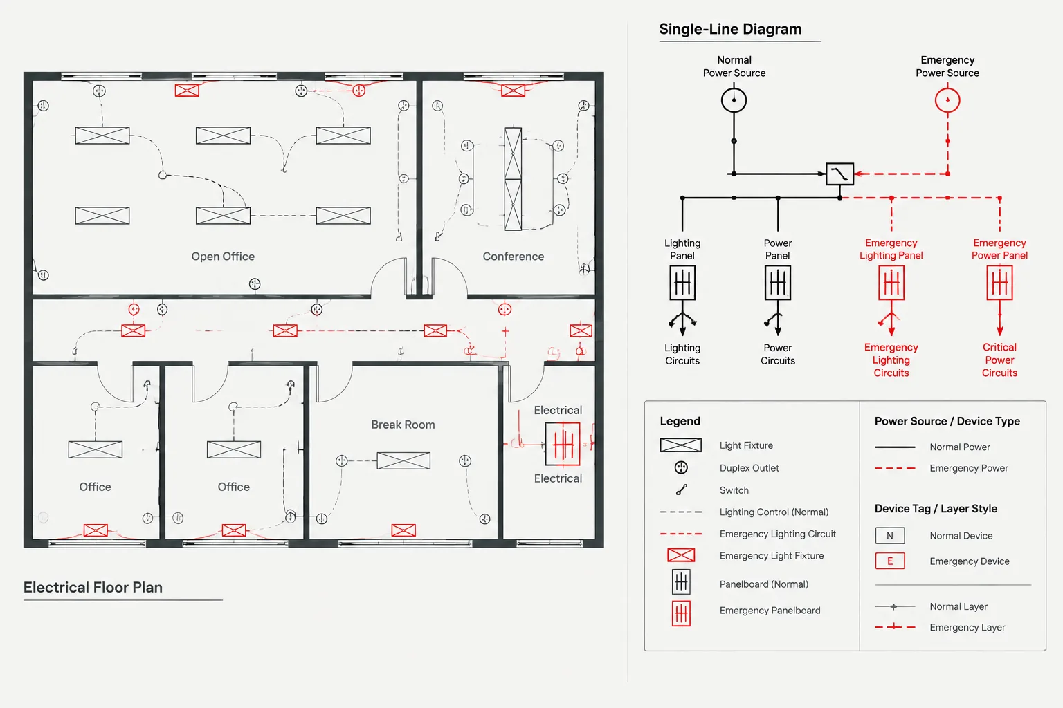
Switch blocks are commonly coordinated with electrical symbol legends, lighting plan graphics, circuit annotations, equipment symbols, and CAD layer standards. On architectural backgrounds, they should remain visually distinct from doors, walls, furniture, and room labels. On schematic drawings, connection logic and device relationships may be more important than physical placement.
These DWG graphics are drafting resources rather than project approval documents. The designer remains responsible for confirming symbol meaning, drawing coordination, applicable requirements, and suitability for the specific documentation set.
Frequently Asked Questions
What should I check after inserting a switch symbol?
Check the block definition, layer, orientation, annotation, visual scale, and plotted appearance. Confirm that the symbol matches the legend used in the same drawing set.
Can the same switch symbol be used on every electrical drawing?
Not always. Floor plans, control diagrams, and schematic drawings may use different graphic conventions. Select the representation that matches the drawing type and project documentation standard.

Should switch blocks be exploded for editing?
Usually, maintaining a reusable block definition supports consistency and easier updates. If geometry must be modified, consider editing a controlled copy or creating a clearly named project-specific definition.
How should switch symbols be organized in AutoCAD?
Use clear block names, appropriate electrical layers, consistent insertion practices, and coordinated tags. Store reviewed symbols in a managed project or office library so users do not rely on unverified duplicates.
Does a DWG symbol confirm code compliance?
No. A CAD block communicates drawing information, but it does not establish compliance or verify the design. Project requirements and symbol conventions should be reviewed by the responsible design professional.
Leave a Reply
You must be logged in to post a comment.