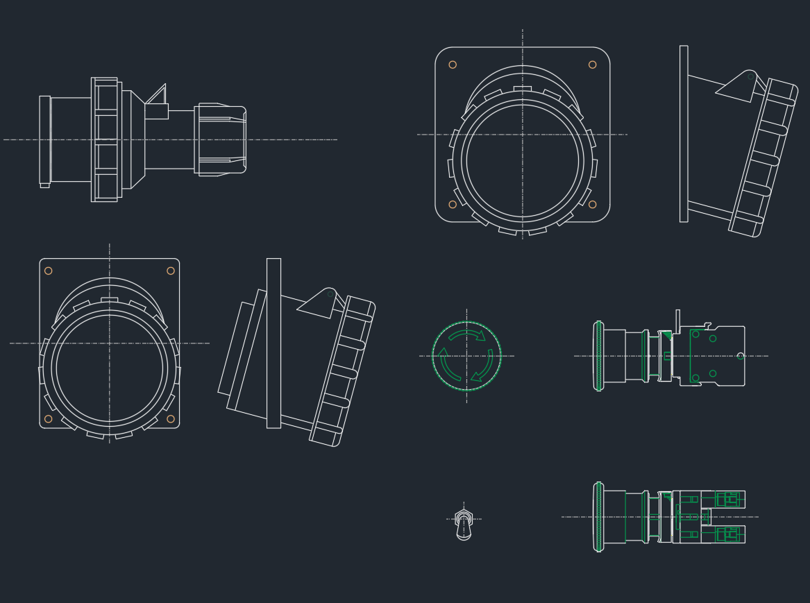
A power plug socket CAD block provides a reusable graphic for identifying a connection point on an electrical plan. It can help maintain consistent symbol appearance across room layouts, equipment plans, and drawing sets while reducing repetitive drafting.
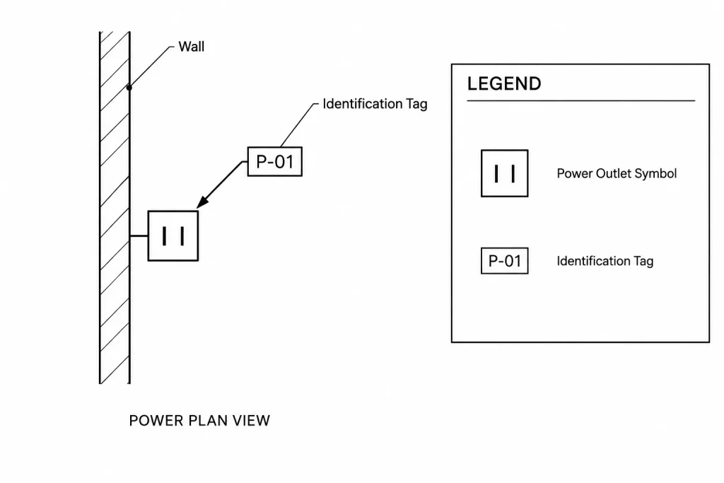
Before using the block, compare its appearance and intended meaning with the project legend. Electrical symbols can vary among firms, clients, drawing types, and regional conventions, so the symbol should be verified rather than interpreted by shape alone.
Download a high-quality Power Plug Socket DWG file, perfect for architects, engineers, and interior designers working on electrical layout plans. This CAD Block offers a detailed and accurate representation of a standard power plug socket, ensuring precision in your designs. The file is fully compatible with AutoCAD and other popular CAD software, making it easy to integrate into your residential, commercial, or industrial electrical projects. Save time on drafting and enhance your project’s professionalism with this ready-to-use Power Plug Socket DWG file, ideal for both 2D and 3D applications.
Please log in or register to download this file.
Using the Power Plug Socket Block in a Drawing
Insert the DWG content into the appropriate electrical or power-plan file, then confirm its insertion point, orientation, scale, and layer assignment. The block should remain legible at the sheet’s intended plotting scale and should not obscure walls, equipment, dimensions, or room annotations.
Where several socket or outlet types appear on the same plan, use tags or keyed notes to distinguish them. The symbol itself should coordinate with the electrical legend, schedules, and related plan notes. Avoid relying on small graphic differences that may disappear when the drawing is printed or exported.
Terminology and Symbol Meaning
In common United States usage, a plug is generally the cord-end component inserted into a receptacle. The term socket may be used more broadly in product descriptions or international drawing libraries. On a building plan, a fixed wall connection point may therefore be labeled as a receptacle, outlet, or socket according to the project’s documentation convention.
This distinction matters when building a symbol legend. A CAD block name can describe the library asset, but the final drawing label should communicate the intended device clearly to reviewers and other disciplines.
Recommended CAD Documentation Checks
- Symbol definition: Confirm what the graphic represents before placing it in the plan.
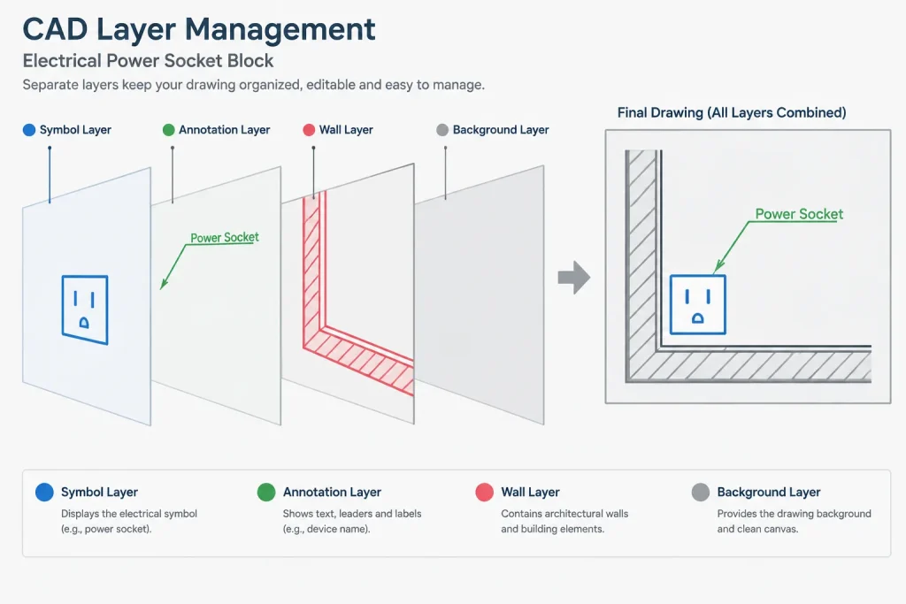
- Layer: Move the block to the office-standard layer used for electrical power symbols.
- Scale: Check visibility at the plotted sheet scale rather than only in model space.
- Orientation: Align wall-related symbols consistently while preserving their readability.
- Attributes: Review any editable tags, descriptions, or identifiers contained in the block.
- Legend coordination: Add or match the symbol in the electrical legend when its meaning is not already defined.
- File cleanup: Inspect imported layers, line types, text styles, and duplicate definitions before adding the asset to a shared library.
Where This Symbol Fits in an Electrical Drawing Set
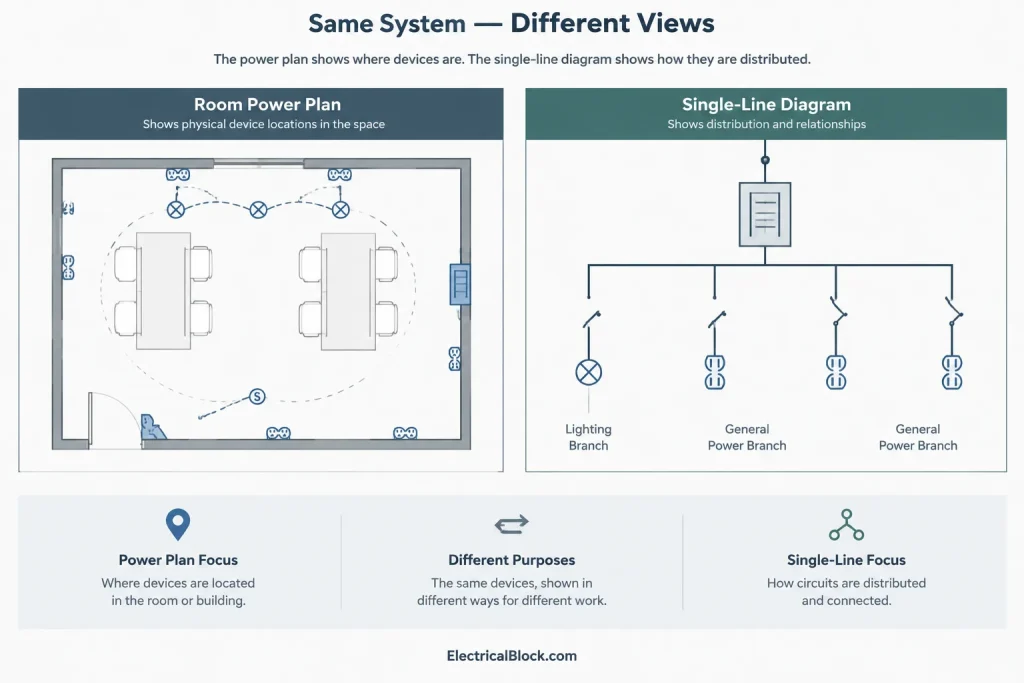
A socket symbol is commonly associated with a power plan or equipment layout. It is different from the simplified device notation used in a single-line diagram, where the emphasis is on distribution relationships rather than physical placement within a room.
Related drafting references include electrical symbol legends, outlet and receptacle symbols, power-plan CAD blocks, equipment connection symbols, panel and distribution diagrams, and CAD layer-management guidance. Reviewing these topics together helps keep plan graphics, identifiers, and diagram conventions coordinated.
Review Before Project Use
A downloaded block is a drafting resource, not a substitute for project design criteria or professional review. Confirm that the symbol, annotation, and drawing context agree with the project requirements and applicable documentation practices. The DWG should also be inspected in the destination CAD application because block behavior, fonts, line types, and other display properties can depend on the receiving file.
Power Plug Socket CAD Block FAQ
Is a power plug the same as a receptacle?
Not usually. In common United States terminology, the plug is attached to a cord, while the receptacle is the fixed device that receives it. CAD libraries may use broader naming, so the project legend should define the symbol’s intended meaning.
Should the block be placed on an electrical layer?
Yes, it should be assigned according to the project or office layer standard. A dedicated power-symbol layer can improve visibility control, plotting, coordination, and later editing.
How should the symbol be scaled?
Use the drawing’s established symbol and annotation conventions. Verify the result at the intended plotting scale and compare it with nearby electrical symbols rather than choosing an arbitrary size.
Can the block be used without a legend?
A familiar symbol may appear self-explanatory, but a legend is advisable whenever the meaning could be confused with another outlet, connection point, or device type. Tags and keyed notes can provide additional clarification.
What should be checked after importing the DWG?
Review the block definition, insertion point, units behavior, layers, line types, text styles, attributes, orientation, and plotted appearance. Remove unrelated imported content before saving the asset into a controlled CAD library.
Does a floor-plan symbol replace a single-line-diagram symbol?
No. A floor-plan symbol communicates physical location and coordination, while a single-line diagram communicates electrical distribution relationships. Each drawing type uses symbols for a different documentation purpose.





Leave a Reply
You must be logged in to post a comment.