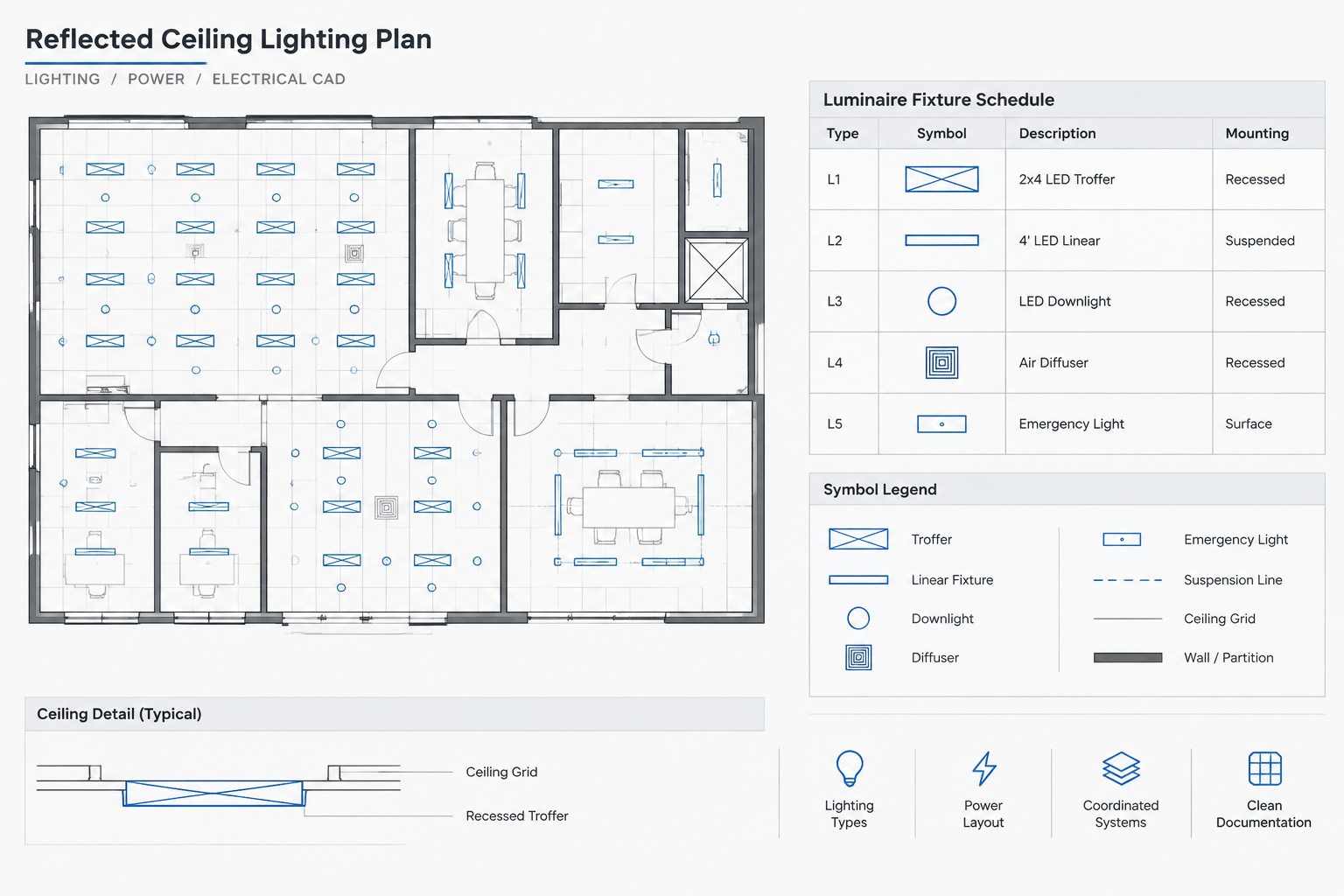
A lighting fixture schedule is more than a list of luminaires. It is a coordination tool connecting fixture symbols on the electrical drawings with product descriptions, mounting conditions, controls, details, and other project documents. When the schedule and plans disagree, readers may not know which information governs.
A reliable lighting fixture schedule CAD workflow starts with clearly defined type marks and a controlled source of information. It then maintains those identifiers across floor plans, reflected ceiling plans, schedules, details, and revisions. The goal is not to place every product characteristic into one table. The goal is to give each fixture type a stable identity and direct the reader to the right supporting information.
What a Lighting Fixture Schedule Communicates
The schedule identifies the fixture types used in the drawing set and summarizes the information needed to interpret them. Depending on the project, the table may include a general description, mounting method, light source information, electrical characteristics, control notes, emergency designation, and remarks.
The schedule should not be confused with a lighting control schedule or panel schedule. These documents answer different questions:
- Fixture schedule: What luminaire type does the plan symbol represent?
- Control schedule: How is a room, zone, or lighting load intended to operate?
- Panel schedule: Where is the associated electrical load documented in the distribution system?
- Lighting plan: Where are fixtures placed, tagged, circuited, and associated with control devices?
These documents should coordinate, but they should not be combined simply to reduce the number of tables. Overloaded schedules are difficult to revise and often mix product, circuit, and sequence information.
Establish a Fixture Type Marking System
Every scheduled fixture type needs a unique and durable identifier. A type mark may use letters, numbers, or a project-specific combination. The exact format matters less than consistency and readability.
A useful type mark identifies a fixture family without attempting to encode every characteristic. For example, embedding mounting, output, control protocol, emergency function, room name, and product data into a single identifier can make the mark difficult to read. It also forces widespread retagging when one characteristic changes.
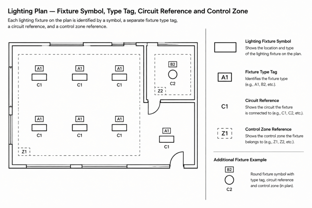
Keep Type Marks Separate from Other References
A fixture type mark should not be mistaken for:
- A circuit or branch designation
- A lighting control zone
- A switch reference
- A room number
- A detail or sheet reference
- A product catalog number
These references may appear near the same fixture, but they serve different documentation purposes. Separate graphic conventions help readers recognize each one.
Define Variants Deliberately
Two fixtures that look similar on plan may require different type marks when their documented characteristics differ. Examples include distinct mounting conditions, optics, finishes, control interfaces, emergency functions, or environmental applications. Conversely, a minor drawing variation does not automatically justify a new fixture type. The design team should determine whether the difference affects procurement, installation documentation, coordination, or intended performance.
Choose Schedule Columns That Support the Project
Schedule content should be tailored to the drawing set and coordinated with the specifications or approved project criteria. Avoid adding columns merely because they appeared in an older template.
| Schedule field | Drafting purpose | Coordination concern |
|---|---|---|
| Type mark | Connects plan tags to a schedule row | Must remain unique and consistent |
| Description | Provides a concise fixture summary | Should not conflict with detailed product documentation |
| Mounting | Clarifies the intended installation condition | Coordinate with ceiling, wall, structure, and details |
| Light source or module | Describes the scheduled source concept | Use terminology consistent with project criteria |
| Electrical data | Supports drawing and load coordination | Verify against current product and design information |
| Controls | Identifies required compatibility or a control reference | Coordinate with diagrams, sequences, and device schedules |
| Emergency designation | Distinguishes fixtures associated with emergency operation | Coordinate with power source and system diagrams |
| Remarks | Records limited type-specific notes | Avoid turning the cell into an unstructured specification |
Do not populate technical values from memory or from an unverified legacy schedule. Product data, design calculations, and current project documentation should be the source. If information is unresolved, use a controlled placeholder that is easy to find during quality review rather than guessing.
Coordinate Schedule Rows with CAD Plan Symbols
A lighting plan commonly uses a symbol to show fixture geometry and a nearby tag to identify the scheduled type. The graphic symbol and the type mark should be treated as related but separate information. Different fixture types can share a similar plan symbol, while one fixture type may need different representations in plan, elevation, or detail.
Use Blocks Without Hiding Design Intent
A CAD block can improve consistency by grouping the fixture symbol, tag, and optional attributes. However, the block should remain readable at the intended plotted scale. Avoid placing so much data inside the block that tags overlap ceiling grids, dimensions, control lines, or architectural elements.
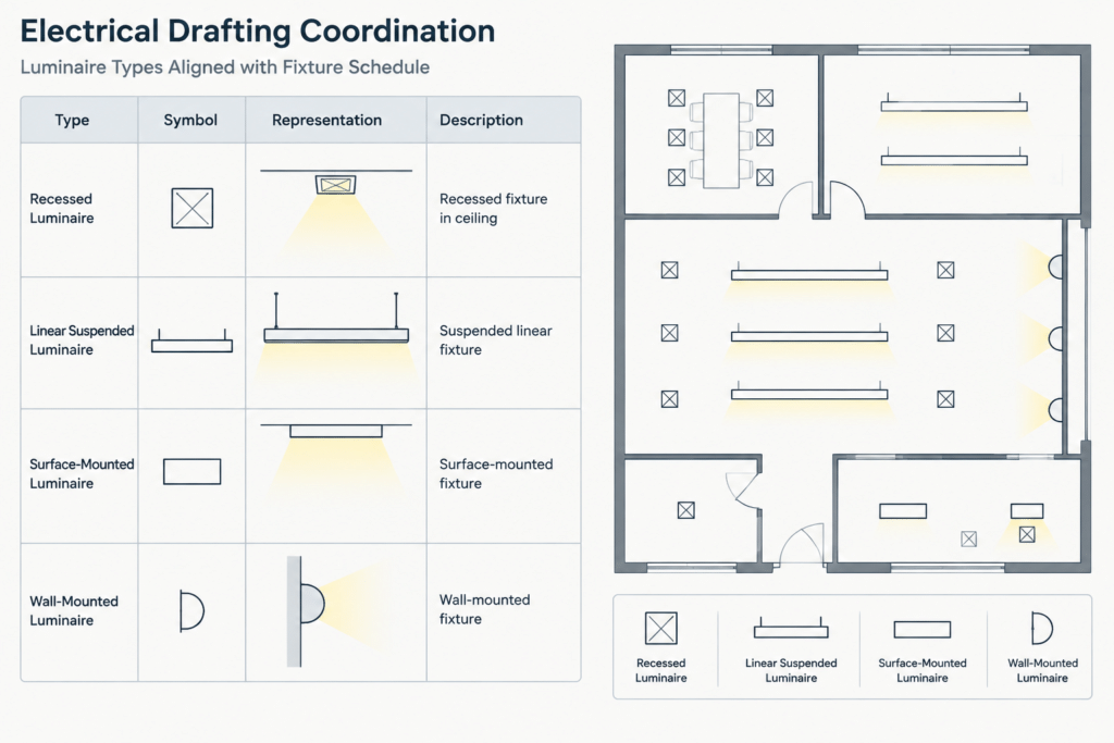
If attributes are used, establish which values are authoritative. A type mark stored in a block attribute should match the schedule source. Manually typing the same identifier into several unrelated objects creates more opportunities for mismatch.
Account for Orientation and Geometry
Linear and directional fixtures may need orientation that reflects their actual design intent. Rotating a symbol should not rotate text into an unreadable position or change the meaning of a directional graphic. Use block construction and annotation settings that preserve legibility while allowing the fixture geometry to follow the layout.
Connect Fixtures to Lighting Controls
A fixture schedule can state control compatibility or point to a control requirement, but it usually should not carry the complete operating sequence. Control zones, sensors, switches, relays, dimming interfaces, and sequence notes may be documented through separate tags, diagrams, schedules, or narratives.
During coordination, confirm that:
- Control references used on plans exist in the corresponding schedule or diagram.
- Fixture types are compatible with the documented control concept.
- Normal and emergency operating intent is not implied only by color.
- Control lines and zone graphics remain distinguishable from circuiting.
- Room-based control notes agree with the fixture types shown in that room.
Color can assist the drafting team, but issued drawings should remain understandable under the project’s intended plotting and reproduction conditions.
Coordinate Mounting Conditions and Details
A schedule entry such as recessed, surface, suspended, wall-mounted, or structure-mounted is only the beginning of coordination. The background drawings may contain several ceiling systems, exposed structure, bulkheads, equipment zones, or special architectural conditions.
Review each fixture type against the locations where it appears. If one type is used in materially different conditions, determine whether a detail, note, or separate type is needed. Do not assume that a generic CAD symbol proves physical compatibility with a ceiling system or surrounding construction.
Detail references should be selective. A standard condition may be covered by coordinated project documentation, while an unusual interface may need a dedicated callout. When details are used, verify that the type mark, mounting description, and depicted condition agree.
Manage Existing, New, and Removed Fixtures
Renovation work requires an additional status layer. A fixture type and a construction status are different concepts. A type mark describes what the fixture is; status identifies whether it is existing to remain, removed, relocated, or new work.
Represent status through the project’s layer, linetype, phase, note, or graphic conventions rather than creating an uncontrolled set of nearly identical schedule rows. If an existing fixture receives a documented modification, clarify whether it remains an existing type, becomes a revised type, or requires a specific note.
A Practical CAD Scheduling Workflow
- Create the type register. Start with a controlled list of fixture types and provisional identifiers.
- Define schedule fields. Include only columns supported by the project’s documentation needs.
- Build or select plan symbols. Confirm that each symbol remains clear at its plotted scale.
- Place fixtures and tags. Keep type tags legible and separate from circuit and control references.
- Coordinate backgrounds. Review ceilings, walls, casework, structure, and equipment for conflicts.
- Add control and circuit information. Use distinct conventions and coordinate references across drawings.
- Check supporting details. Verify unusual mounting and interface conditions.
- Validate the schedule. Compare every used type mark with the schedule and identify unused rows.
- Review revisions. Track renamed, added, deleted, and substituted types across the entire set.
Quality-Control Checks Before Issue
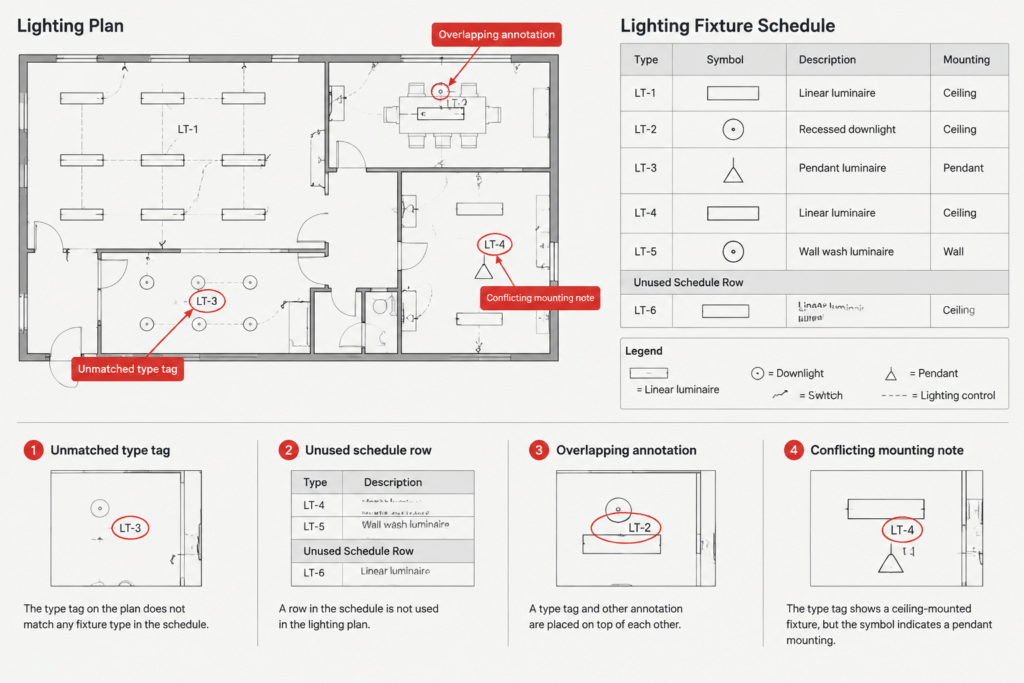
A focused comparison between plans and the fixture schedule catches many common documentation errors. Review the drawing set for:
- Plan tags with no matching schedule row
- Schedule rows that are no longer used
- Duplicate type marks assigned to different fixtures
- Inconsistent descriptions across schedules and details
- Missing or conflicting mounting information
- Emergency designations that disagree with diagrams or plans
- Control notes that reference obsolete fixture types
- Fixture tags obscured by ceiling grids, hatches, or room text
- Legacy product data carried forward without verification
- Revision clouds or notes that do not cover all affected views
The final schedule should function as an index to coordinated design information, not as an isolated table. Stable type marks, restrained schedule content, readable CAD symbols, and disciplined revision control make lighting plans easier to interpret and maintain. Every real project still requires verification against its current design criteria, specifications, product information, and applicable requirements.




Leave a Reply
You must be logged in to post a comment.