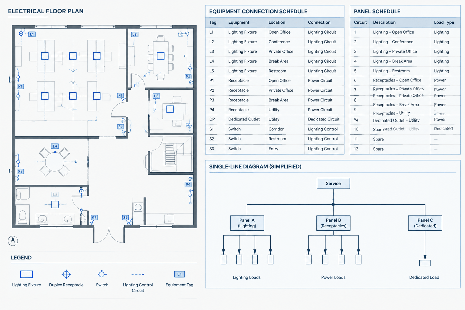
An electrical equipment connection schedule organizes the information needed to connect equipment shown on power plans. It can link an equipment tag to its location, electrical source, connection type, circuit reference, and related coordination notes. Used well, the schedule becomes a practical bridge between the plan graphics and the rest of the electrical drawing set.
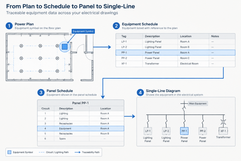
The schedule is not a substitute for engineering calculations, verified product data, or project requirements. Its purpose is to present approved design information consistently and make discrepancies easier to find. The drafting workflow should therefore emphasize traceability: a reader should be able to move from an equipment symbol to its schedule row, then to the applicable panel schedule, single-line diagram, or detail.
What belongs in an equipment connection schedule?
The exact columns depend on the project, but each field should answer a clear documentation question. Avoid adding columns simply because they appeared in an older template. Empty or ambiguous fields make the schedule harder to maintain and may suggest that information has been verified when it has not.
| Typical field | Documentation purpose |
|---|---|
| Equipment tag | Provides the primary identifier used on plans, schedules, and diagrams. |
| Description | States the equipment function in concise, recognizable language. |
| Location or area | Helps distinguish similar items and supports plan coordination. |
| Electrical source | Identifies the supplying panel, distribution equipment, or other documented source. |
| Circuit or feeder reference | Connects the equipment row to the applicable circuit designation. |
| Connection representation | Clarifies whether the plan shows an outlet, disconnecting device, connection point, control interface, or another documented arrangement. |
| Load information | Records verified design data where the project documentation requires it. |
| Drawing or detail reference | Directs the reader to a diagram, enlarged plan, control schematic, or installation detail. |
| Remarks | Captures short, equipment-specific coordination information that does not fit another field. |
Project teams may use different terminology for the same concepts. Define headings in plain language and keep them consistent across sheets. If a field is not applicable, use the project’s established notation rather than leaving readers to guess whether the cell was overlooked.
Start with a stable equipment identification system
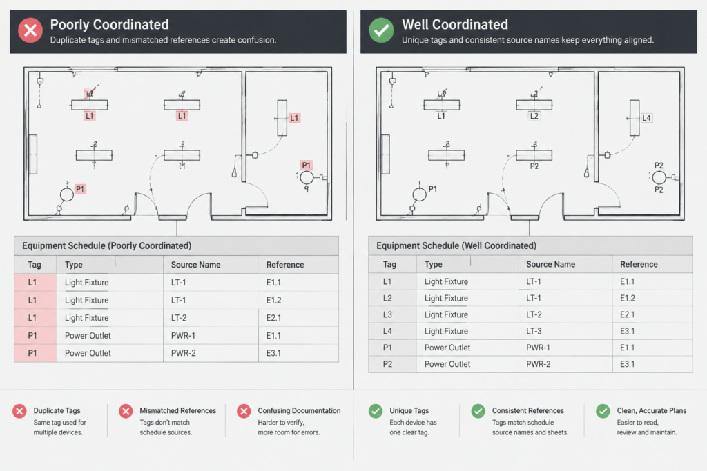
A reliable schedule begins with unique tags. Each scheduled item should have one primary identifier, and that identifier should appear wherever the item is referenced. Similar equipment can share a description, but it should not share an identifier if the items require separate connections or coordination.
Tags should remain readable when a plan is plotted at its intended sheet scale. Keep the tag close enough to the symbol to make the association obvious, but do not place it over walls, dimensions, architectural room names, or other disciplines’ annotations. A leader may be appropriate in a dense area, provided it terminates clearly and does not resemble a circuit line.
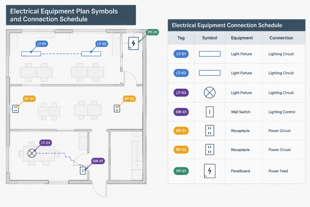
Before creating tags, check whether the project already has identifiers in a mechanical, plumbing, process, kitchen, laboratory, or owner equipment schedule. Reusing the approved equipment ID usually improves coordination. Creating a second, unrelated naming system can make it difficult to compare drawings.
Build the schedule from coordinated source information
Do not populate electrical characteristics by estimating from the equipment name or copying a visually similar item from another project. Gather information from the current design criteria, approved equipment data, consultant schedules, and documented coordination decisions. Mark unresolved entries according to the project’s quality-control procedure.
Use a controlled drafting sequence
- Collect the equipment list: Identify all items that require an electrical connection or an electrical coordination note.
- Normalize descriptions: Use consistent names while preserving the equipment IDs established by the project team.
- Locate each item: Confirm that the scheduled equipment appears on the relevant floor plan, roof plan, site plan, enlarged plan, or diagram.
- Assign documented sources: Coordinate source and circuit references with panel schedules and distribution drawings.
- Add detail references: Point to connection details or control diagrams only when those references exist and apply.
- Review unresolved information: Make missing data visible internally so it is not silently issued as complete.
This sequence separates data collection from graphic production. It also reduces the risk of drafting a polished schedule around incomplete or outdated information.
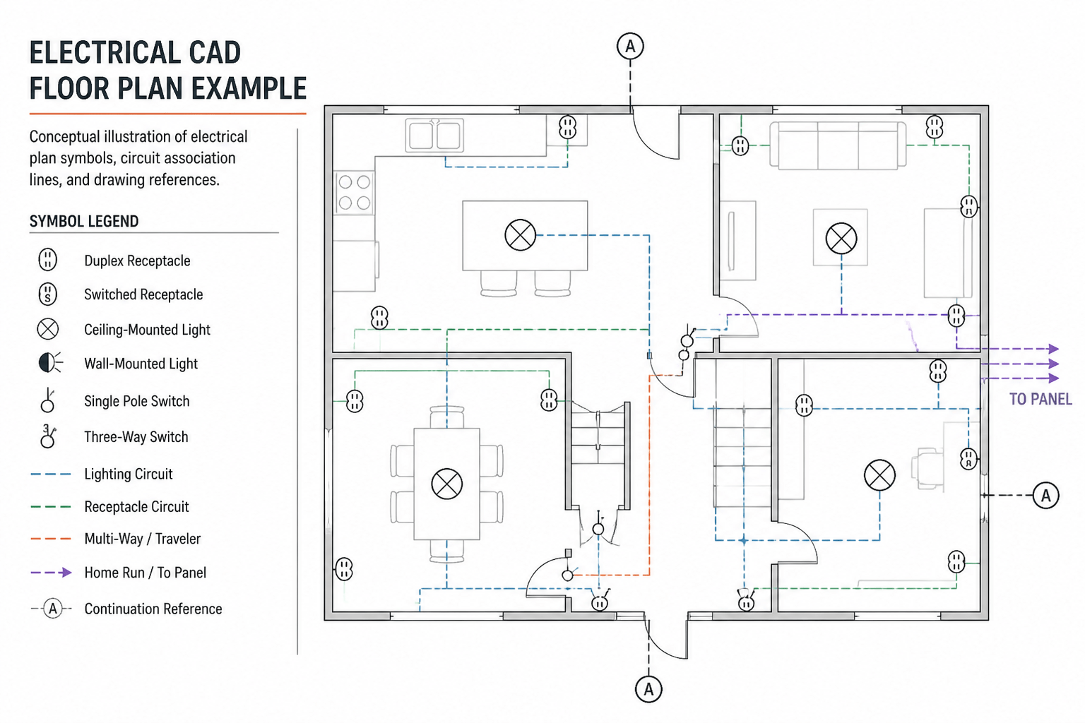
Coordinate the schedule with power plans
Every active schedule row should have a corresponding plan or diagram representation unless the drawing set clearly explains another documentation method. Conversely, equipment shown as requiring a connection should not be absent from the schedule when the schedule is intended to be comprehensive.
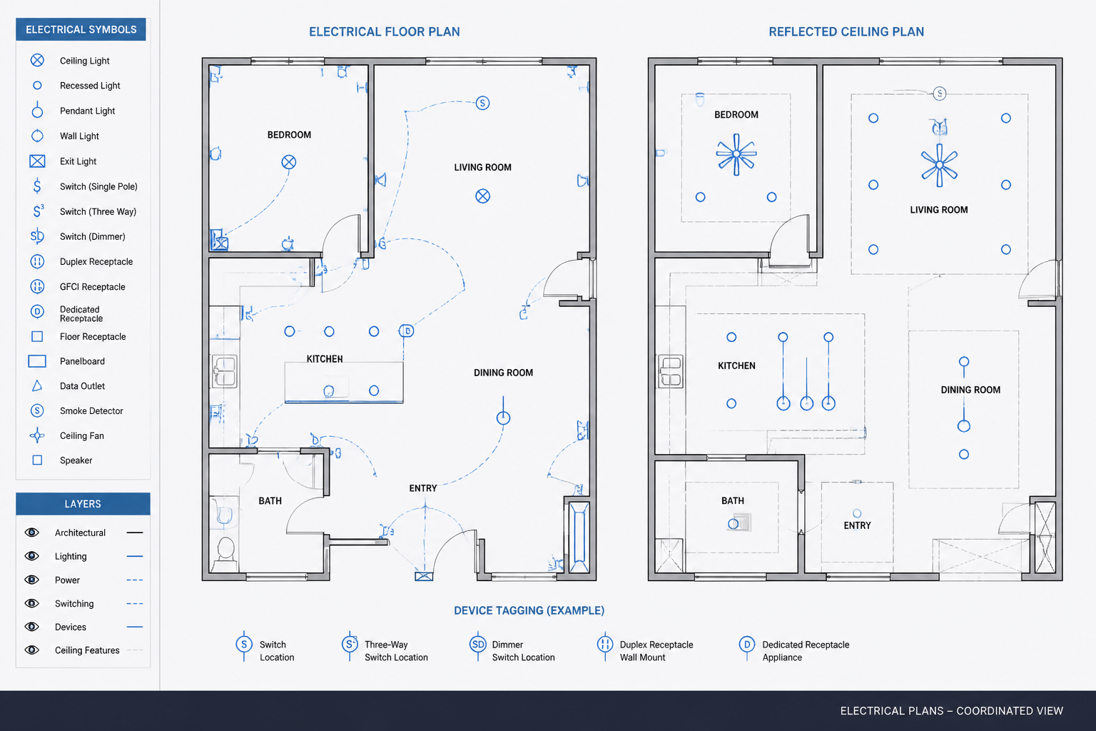
Check symbol type as well as tag presence. A schedule row may indicate one connection concept while the plan symbol suggests another. The symbol, nearby note, circuiting, and schedule entry should communicate a compatible design intent. Where several connections serve one equipment assembly, distinguish them with separate identifiers or clearly related sub-tags rather than stacking unclear annotations around one symbol.
Also review background alignment. An equipment symbol can remain in the CAD file after the architectural or consultant background has moved. Verify the apparent location against the latest coordinated reference, especially in rooms with dense equipment layouts.
Coordinate sources with panel schedules and single-line diagrams
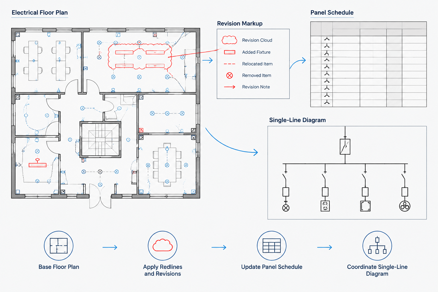
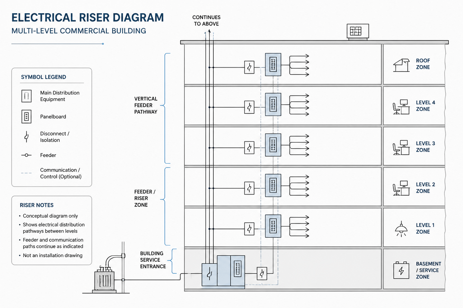
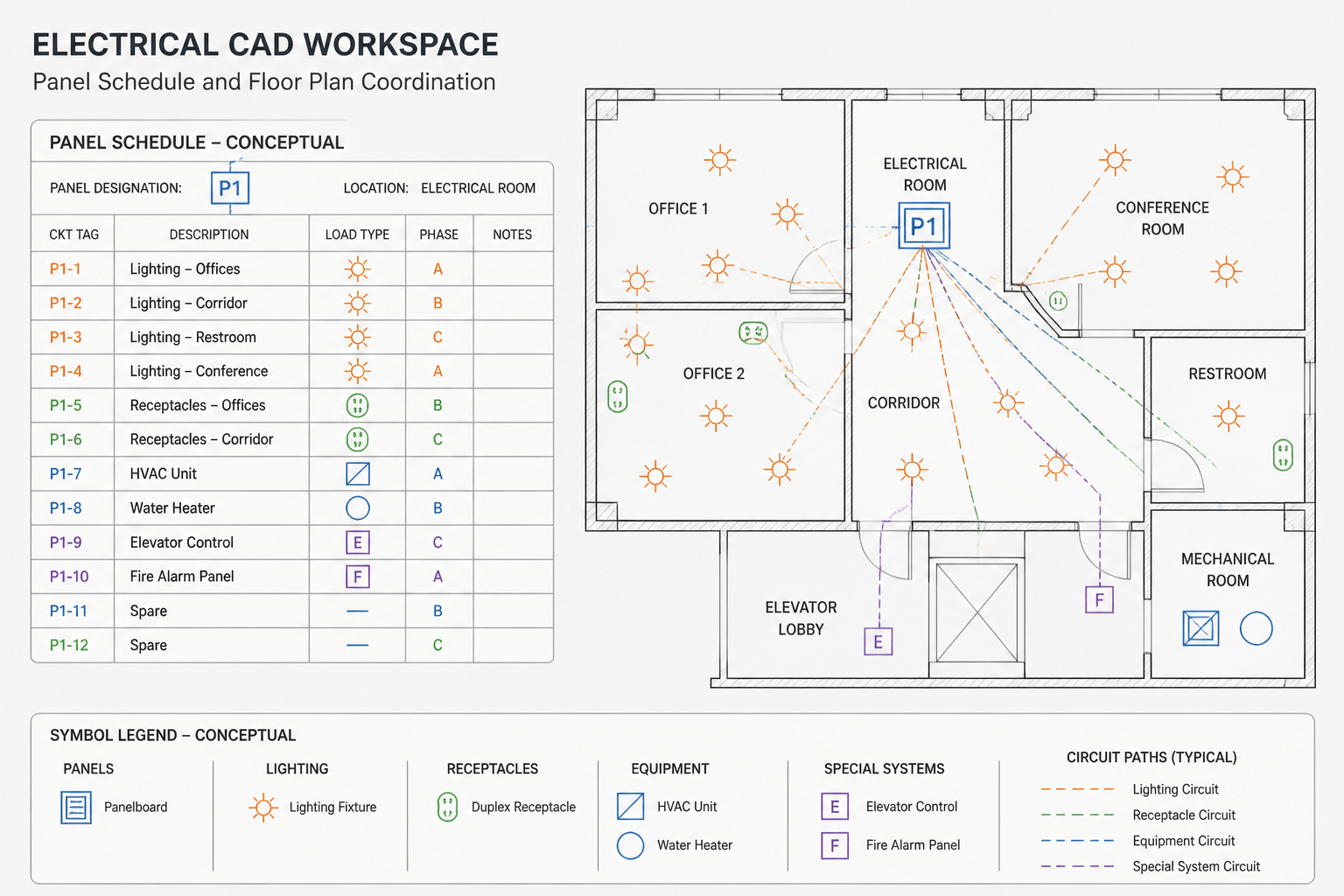
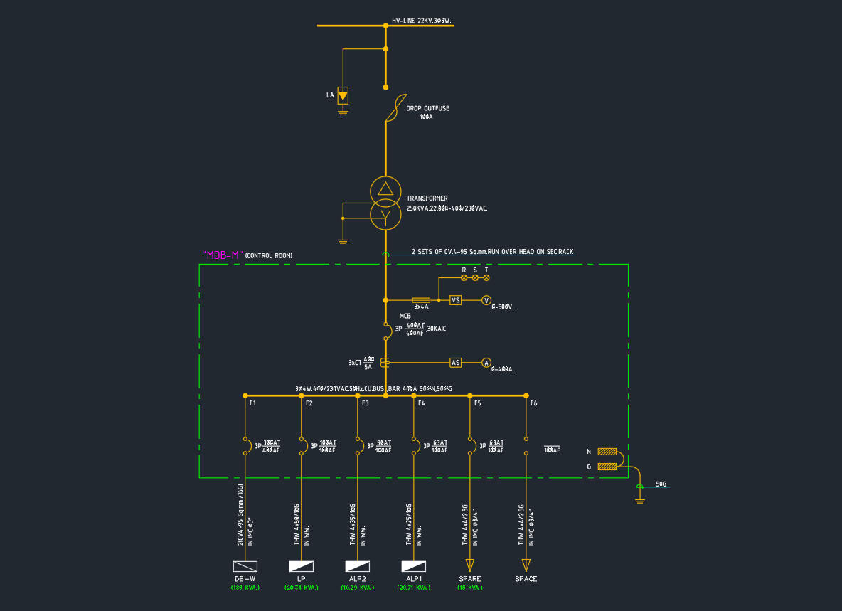
The equipment connection schedule, panel schedule, and single-line diagram describe different views of the same distribution relationships. Their references should agree.
- The source designation in the equipment schedule should match the designation used in the panel schedule or distribution documentation.
- The circuit reference on the plan should match the circuit assigned in the panel schedule.
- Distribution equipment names should remain consistent between plans, schedules, and single-line diagrams.
- Feeder or upstream relationships should not be inferred from a copied schedule when the current single-line diagram shows a different arrangement.
- Spare, future, removed, and existing connections should use the project’s established status language consistently.
A useful quality-control method is to review in both directions. First, trace each equipment schedule row to the plan and its source. Then start from each relevant panel schedule entry and trace it back to the connected equipment. The reverse check often finds duplicate circuit references, obsolete tags, and equipment omitted during background updates.
Separate connection data from installation detail
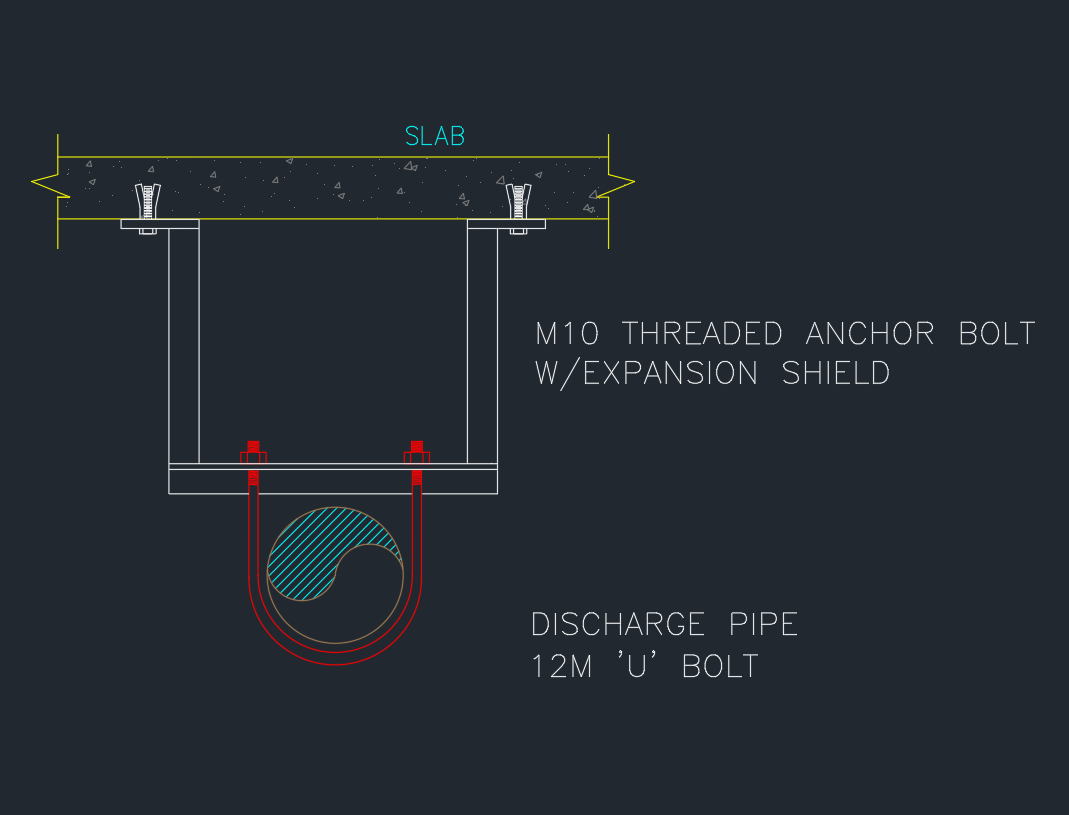
A schedule should remain scannable. Long installation narratives, repeated general requirements, and complex control sequences usually belong in notes, specifications, diagrams, or details. The schedule can point to those documents through concise references.
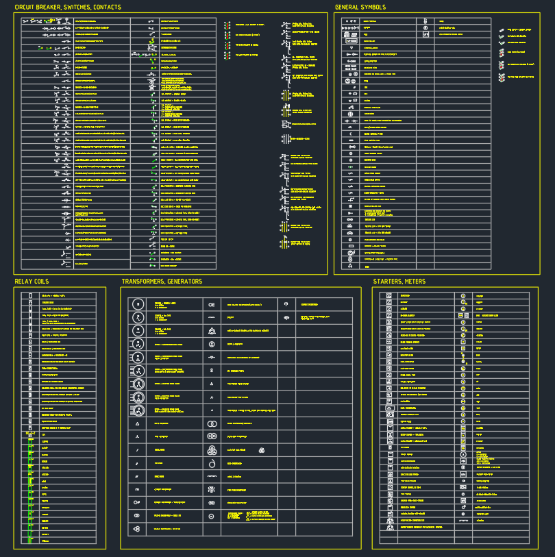
For example, a connection row may identify a related disconnecting device or control interface without attempting to depict every conductor and control function. If the project requires a schematic explanation, create or reference an appropriate diagram. Avoid using a general-purpose CAD block as proof of the final connection arrangement; a block is a graphic resource, not verified project data.
Draft the schedule for readability
Whether the schedule is drawn with CAD lines and text or generated through another documentation workflow, its plotted appearance matters. Use a clear heading hierarchy, consistent text alignment, adequate column spacing, and predictable abbreviations. Descriptions generally benefit from left alignment, while short identifiers can be centered if that matches the office standard.
Keep rows visually distinct without making every grid line equally prominent. Header divisions and major group breaks can carry more visual emphasis than individual data cells. If the schedule spans multiple sheets, repeat the header and clearly indicate how the continuation is organized.
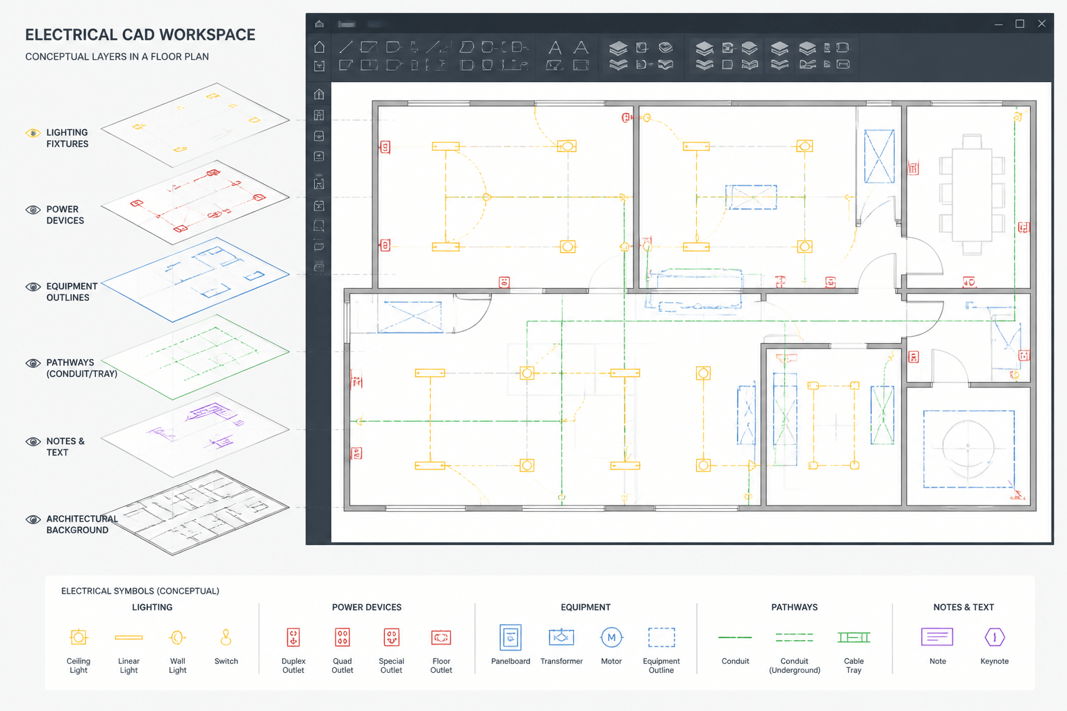
Place schedule graphics and text on appropriate documentation layers. Avoid placing the entire table on one layer if the project requires independent control of borders, headers, notes, and revision graphics. Whatever layer structure is used, test the actual plot output rather than relying only on model-space color.
Manage changes without breaking references
Equipment schedules are vulnerable to late revisions because a single change can affect several drawings. Moving equipment may alter its area reference. Replacing equipment may change verified connection data. Reassigning a source can affect the plan circuit tag, panel schedule, load documentation, and single-line diagram.
When a scheduled item changes, perform an impact review rather than editing only the visible cell. Search the drawing set for the equipment tag and source designation, then inspect every relevant occurrence. If an item is removed, determine whether its row should be deleted, retained with a documented status, or transferred to demolition information according to the project’s drawing conventions.
Final coordination checklist
- Each equipment tag is unique and legible.
- Descriptions match the coordinated equipment list.
- Scheduled items appear in the expected plan or diagram location.
- Plan symbols communicate the same connection intent as the schedule.
- Source names agree with panel schedules and single-line diagrams.
- Circuit references agree between plans and schedules.
- Detail references exist and point to applicable information.
- Unverified data is not presented as confirmed design information.
- Removed or revised equipment has been checked throughout the drawing set.
- The schedule remains readable in the plotted sheet set.
A well-coordinated electrical equipment connection schedule does more than list equipment. It creates a traceable documentation path through plans, schedules, and diagrams. By using stable tags, verified source information, concise fields, and bidirectional quality checks, the drafter can make connection information easier to review and less likely to become disconnected during revisions.
Leave a Reply
You must be logged in to post a comment.