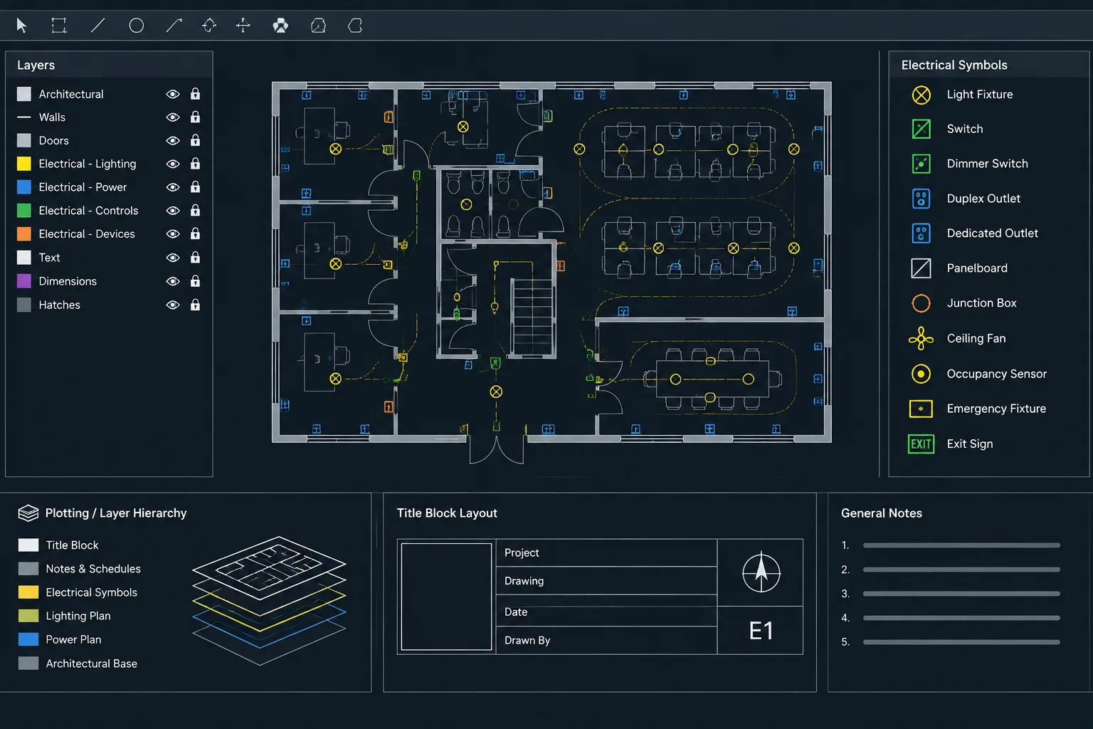
A consistent electrical drawing set begins with repeatable drafting controls. An electrical CAD template gives the project team a common framework for organizing model content, references, annotations, sheets, and plotted output without preselecting project-specific electrical solutions.
This guide explains how to structure that framework, test it under realistic documentation conditions, and manage revisions without turning the template into an uncontrolled collection of legacy content.
An electrical CAD template is more than an empty drawing with a title block. It is a controlled starting point for layers, annotation, symbols, layouts, reference files, plotting, and project data. A well-planned template reduces repetitive setup and helps multiple drafters produce drawings that look and behave consistently.
The template should establish drafting conventions without embedding project-specific design decisions. Circuiting, equipment ratings, feeder information, room data, and construction notes still require project review. Likewise, a CAD block included in a template is only a graphical resource; its presence does not establish that the represented device is appropriate for a particular installation.
Define the Template’s Purpose Before Building It
Start by deciding what the template is expected to create. A single universal file may become overloaded if it attempts to support every drawing type. Many offices benefit from a small family of related templates rather than one file containing every possible layer and layout.
Possible template categories include:
- Lighting and lighting-control plans
- Receptacle and small-power plans
- Equipment power and distribution plans
- Single-line and riser diagrams
- Electrical site or utility plans
- Details, elevations, and schedules
These files can share the same layer logic, text styles, title block structure, and plotting conventions while retaining drawing-type-specific content. This keeps each starting file understandable and reduces the temptation to copy an old project that may contain outdated notes or hidden geometry.
Establish Units and Coordinate Assumptions
Document the intended drawing units and how they relate to referenced backgrounds. An electrical floor-plan template should align with the unit convention used by the architectural and consultant files. Diagram templates may use a different graphical arrangement because a single-line diagram is generally organized by electrical relationships rather than physical building coordinates.
The template should also state the expected coordinate workflow. For example, plan drawings may be created relative to a shared project origin, while details and diagrams may use a local origin. Recording this assumption in a nonplotting instruction area can prevent arbitrary movement of referenced backgrounds.
Avoid placing representative building geometry far from the intended origin merely to demonstrate the template. Sample content can accidentally be retained in live project files or create unnecessary drawing extents.
Create a Focused Electrical Layer System
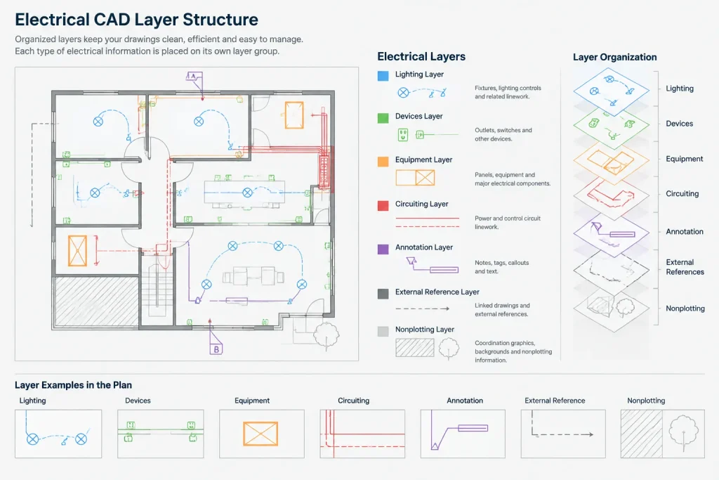
Layer names should describe the type and purpose of the objects they contain. Separate layers are commonly useful for devices, lighting fixtures, equipment, circuit graphics, raceways, tags, notes, references, and nonplotting coordination information. Existing-work and demolition graphics may also need distinct controls when renovation projects are common.
Do not create a separate layer for every individual block unless that separation supports visibility, plotting, or editing. Excessive layers make the file harder to manage, while too few layers prevent useful control. The right structure reflects how sheets are actually composed and reviewed.
| Layer group | Typical content | Reason for separation |
|---|---|---|
| Devices and fixtures | Receptacles, switches, luminaires, sensors, and similar symbols | Controls discipline graphics independently from backgrounds |
| Equipment | Panels, transformers, disconnects, and connection points | Supports equipment coordination and selective display |
| Circuiting and routes | Circuit lines, home runs, conduit paths, or cable tray paths | Allows route graphics to be reviewed without hiding devices |
| Annotation | Tags, leaders, notes, and callouts | Separates explanatory information from physical symbols |
| References | External backgrounds and consultant overlays | Provides predictable visibility and plotting control |
| Nonplotting information | Working boundaries, review clouds, or coordination guides | Prevents temporary drafting aids from appearing in an issue set |
Assign object properties through layers wherever practical. Individually overridden colors, linetypes, and lineweights can make a template difficult to audit and may produce inconsistent plots.
Coordinate Text, Leaders, and Dimensions
Create a limited set of annotation styles with clear purposes. Typical categories may include general notes, compact plan labels, detail titles, section references, and schedule text. The exact plotted appearance should be confirmed using the office’s normal sheet sizes and output process rather than judged only on screen.
Text styles should use fonts that are available to the intended project team and deliverable recipients. If a drawing depends on an uncommon font, substitutions can change spacing, wrapping, and alignment. The template should favor portability unless a controlled project environment guarantees the required resources.
Leader and dimension styles should match the annotation system. Check arrowheads, landing behavior, text placement, units, precision, and scaling assumptions. Electrical plans may contain few dimensions compared with architectural drawings, but dimensions used for equipment locations, coordination zones, or enlarged plans still need a consistent visual hierarchy.
Prepare a Controlled Symbol Starter Set
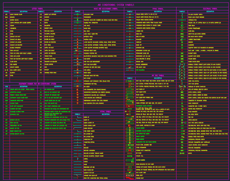
A template can contain commonly used electrical symbols, but the starter set should remain small and well governed. Include only blocks that have been reviewed for units, insertion points, layer behavior, attribute structure, and plotting clarity.
Useful checks for every starter block include:

- Does the insertion point support predictable placement?
- Does the block rotate and mirror without producing misleading graphics?
- Are nested objects assigned properties that respond correctly to the drawing standard?
- Are attributes clearly named and presented in a logical editing order?
- Is the symbol intended for a plan, elevation, detail, or diagram?
- Can the block be distinguished from similar devices when plotted?
Do not fill the template with an entire block library. A managed external library is easier to update, classify, and approve. The template should provide dependable starting symbols and a clear path to the larger collection.
Build Layouts Around Real Deliverables
Paper-space layouts should reflect the drawing sheets the team actually issues. Each layout can include the appropriate title block, viewport conventions, sheet metadata fields, and plotting assumptions. Avoid creating numerous speculative layouts that users must delete from every project.
Check that viewport layers can be controlled without changing the underlying model globally. A lighting plan and a power plan may reference the same architectural background but require different visible electrical content. The template should support that separation while avoiding duplicate model geometry.
Title block data should be divided into stable office information and editable project information. Project name, sheet title, sheet number, issue data, and professional information should not be left as realistic-looking sample content. Use unmistakable placeholders so incomplete fields are easier to detect during review.
Define the External Reference Workflow
An electrical plan template should anticipate architectural, structural, mechanical, civil, or other referenced files. Create a documented location for xrefs and establish whether the workflow expects relative paths, a defined project folder structure, or another controlled method.
Reference files should remain references rather than being absorbed into the electrical model without a deliberate reason. Keeping consultant backgrounds separate makes updates easier to identify and reduces ownership confusion. The template may include an xref layer structure and a nonplotting note explaining insertion, origin, and update expectations, but it should not include a copied project background.
Add Practical Quality-Control Aids
Quality-control content can be built into the template without appearing on issued sheets. A nonplotting checklist area may remind users to review unresolved placeholders, missing references, unexpected layer overrides, duplicate symbols, disconnected circuit graphics, drawing extents, and title block fields.
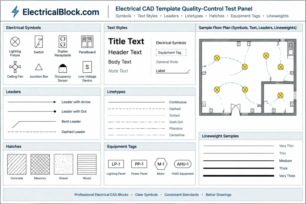
A compact test panel is also useful during template maintenance. It can contain representative text, leaders, linetypes, hatches, symbols, and lineweights. Plotting this panel helps reveal changes caused by style edits or resource substitutions. Keep it on a clearly identified nonissue layout or in a separate validation file so it cannot be mistaken for project content.
Test the Template as a Small Drawing Set
Do not approve a template based only on an empty opening screen. Use it to create a small test set containing a plan, a diagram, a detail, and a schedule. Attach a sample background, place several symbols, edit attributes, create viewports, and produce the same output formats expected from a live project.
Review the result at its intended plotted scale. Confirm that:
- Symbols remain recognizable among background graphics.
- Text and tags have a consistent hierarchy.
- Dashed and centerline patterns display predictably.
- Layer controls produce the intended plan types.
- Title block fields are easy to complete and audit.
- Referenced files can be updated without manual realignment.
- Exports do not contain unwanted construction geometry or template instructions.
Control Template Revisions
Treat the electrical CAD template as a managed office resource. Assign responsibility for reviewing requested changes, testing them, and communicating updates. A template should not change silently in the middle of a project because even a beneficial revision can cause differences between sheets created at different times.
Maintain a short change log describing what was modified and why. Existing projects may need to retain their original setup, selectively import improvements, or adopt the revised template at an agreed milestone. The correct approach depends on project requirements and deliverable controls.
A Template Is a Starting System, Not a Finished Design
The best electrical CAD template removes avoidable setup decisions while leaving project decisions visible to the design team. It should make correct drafting behavior easier: predictable layers, readable annotation, controlled symbols, coordinated references, and repeatable layouts.
Keep the file lean, test it through actual drawing production, and review it whenever workflows or deliverable expectations change. A dependable template will not replace engineering judgment or project verification, but it can provide the consistent documentation framework needed to express that work clearly.
Separate Template Rules From Project Content
A useful template defines how information should be documented, not what the electrical design must contain. Layer behavior, annotation styles, block conventions, reference handling, layout structure, and plotting controls are template concerns. Equipment selection, circuit relationships, ratings, installation notes, and coordination decisions belong to the project.
This distinction makes the template easier to reuse and audit. It also reduces the risk that sample notes, placeholder data, or assumptions from an earlier drawing will be mistaken for reviewed design information.
Assign Ownership to Each Template Component
Template maintenance becomes more reliable when responsibility is clear. CAD management may control layers, styles, paths, and plotting resources, while electrical reviewers evaluate symbol meaning, annotation conventions, and drawing-type requirements. Project teams can then report workflow problems without directly changing the shared source file.
Requested changes should be evaluated as system changes rather than isolated drafting preferences. A new layer, block, field, or style may affect visibility, plotting, exports, reference coordination, and existing projects.
Use an Acceptance Workflow Before Release
A template review should examine both appearance and behavior. Open the file in the normal production environment, create representative electrical views, attach expected background types, edit block data, update sheet information, and generate the required deliverables. Reviewers should look for content that is difficult to find, properties that require manual overrides, placeholders that resemble approved data, and instructions that could appear in issued output.
The release copy should contain only approved reusable resources. Experimental blocks, abandoned styles, detached references, imported consultant layers, and realistic sample project information should be removed or moved into a separate development file.
Plan for Existing Projects
Updating the office template does not automatically update drawings already in production. Decide whether an existing project should retain its established setup, import selected resources, or adopt the revised structure through a controlled migration. Mixing old and new conventions without review can create duplicate styles, conflicting layer behavior, and visible differences between sheets.
When a migration is necessary, test it on a copy of the project and compare the resulting plans, diagrams, schedules, and plotted sheets. The goal is not merely to make the file open successfully; it is to preserve drawing meaning and deliverable consistency.
Electrical CAD Template FAQ
What should be included in an electrical CAD template?
Include reusable drafting controls such as approved layers, annotation styles, layout structures, title block placeholders, plotting conventions, reference-file expectations, and a limited set of validated symbols. Keep project-specific design data out of the shared starting file.
Should every electrical drawing type use the same template?
Not necessarily. Related templates can share the same visual and organizational standards while providing content appropriate to plans, diagrams, details, schedules, or site drawings. This is often easier to manage than an overloaded universal file.
Should the complete electrical block library be stored in the template?
A small starter set can be useful, but the complete library is generally easier to govern as a separate managed resource. This allows symbols to be reviewed and updated without filling every new drawing with unused definitions.
How can a team tell whether a template is working?
Test it through an actual documentation workflow rather than reviewing an empty file. Check symbol placement, annotation editing, layer visibility, reference updates, layout behavior, plotting, exports, and the removal of nonissue content.
Why do drawings created from the same template still look inconsistent?
Common causes include manual property overrides, imported styles, uncontrolled block definitions, inconsistent reference files, viewport-specific settings, and project files created from different template revisions. A drawing audit should distinguish template behavior from later project edits.
Can a template replace project quality control?
No. A template can make preferred drafting behavior easier and improve consistency, but it cannot verify electrical design decisions, coordination, equipment suitability, or project-specific requirements.







Leave a Reply
You must be logged in to post a comment.