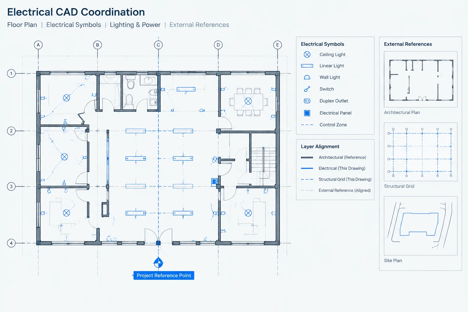
Electrical CAD coordinates provide the shared location framework that allows electrical plans to align with architectural, structural, civil, and mechanical information. A reliable workflow distinguishes the drawing origin from the project reference point, confirms units and orientation, and documents any approved transformation before files are exchanged.
The guidance below helps drafters recognize coordinate discrepancies, verify background placement, and avoid manual corrections that may appear acceptable on a sheet while creating unreliable model-space geometry.
Electrical drawings rarely exist in isolation. Lighting, power, fire alarm, communications, site utilities, and equipment layouts must align with architectural, structural, civil, and mechanical backgrounds. That alignment depends on more than attaching the correct file. Every discipline must also understand the project origin, coordinate basis, orientation, units, and reference procedure.
A coordinate problem may initially look like a simple drafting error: a plan appears far from the expected location, an underlay is slightly rotated, or an electrical file lands correctly in one drawing but not another. If the underlying coordinate method is not identified, moving geometry by eye can create a second coordinate system and make later exchanges unreliable.
This guide explains how to establish and maintain electrical CAD coordinates as part of a controlled documentation workflow. It focuses on drawing organization and coordination rather than any particular CAD platform.
Why Coordinate Control Matters in Electrical CAD
Consistent coordinates allow files from different disciplines to be combined without manually repositioning them for every review. This is important when placing electrical devices against walls, aligning site equipment with civil features, locating penetrations relative to structure, and comparing revised backgrounds.
Coordinate control also supports dependable overlays. When files share an agreed basis, a drafter can replace an architectural background with a newer issue and assess actual design changes. If the background must be moved or rotated each time, it becomes difficult to distinguish a building revision from a reference-placement error.
Common consequences of poor coordinate control include:
- Electrical devices shifting away from walls, rooms, or ceiling features.
- Site lighting, duct banks, or utility equipment appearing in the wrong location.
- Floor plans failing to stack vertically.
- Consultant files requiring unexplained move or rotation values.
- Incorrect comparison results between drawing issues.
- Copied geometry carrying an unintended coordinate offset into another file.
- Teams issuing files that look correct on a sheet but do not align in model space.
Understand the Coordinate Concepts Before Editing
Several related concepts are often described simply as the “origin,” even though they serve different purposes. The project team should identify which point and orientation govern file exchange.
Drawing Origin
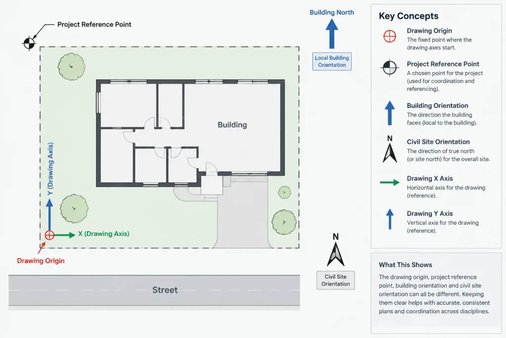
The drawing origin is the base coordinate location within a CAD file. Geometry may be drawn near it or a long distance away, depending on the project setup. The existence of an origin does not by itself establish a shared project coordinate system.
Project Reference Point
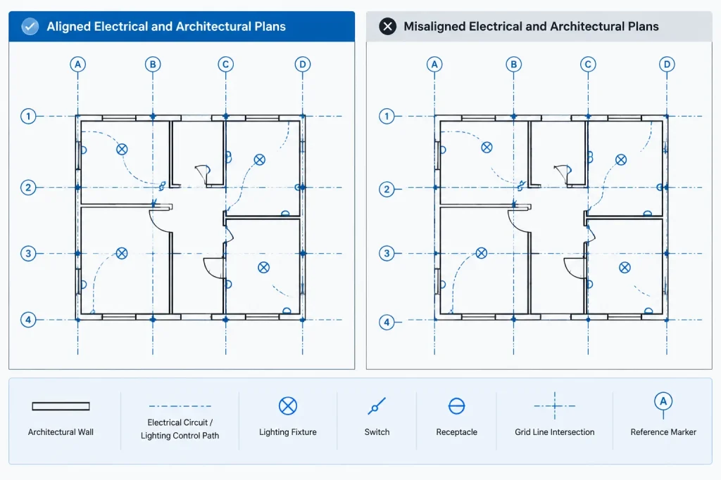
A project reference point is an agreed feature used to check alignment. It might correspond to a building grid intersection, a surveyed control point, or another stable project feature. It should be selected and documented by the project team rather than assumed by an individual drafter.
Survey or Civil Coordinate Basis
Site and utility drawings may use coordinates derived from survey or civil information. These files can be located far from the internal origin and may use a site orientation that differs from a convenient building-plan orientation. Electrical site work should preserve the established basis unless the responsible project team provides a documented transformation method.
Plan Rotation
A building may be displayed horizontally on a sheet even though its actual site orientation is different. A rotated presentation view is not necessarily a new coordinate system. The key question is whether the geometry itself was rotated or whether only the view and sheet presentation changed.
Local Working Coordinates
Some teams use a simplified local basis for building drawings while retaining a separate relationship to survey coordinates. This can be a workable method, but the translation between systems must be deliberate, documented, and consistently applied. An undocumented local offset creates uncertainty during every file exchange.
Establish a Coordinate Control Record
Create a short project coordinate record before developing discipline plans. It can be maintained in the CAD execution documentation, background log, project notes, or another controlled location. The record should describe the method without relying on one person’s memory.
Useful entries include:
- The file or discipline that governs plan alignment.
- The recognized project reference point and how it can be identified.
- The expected drawing units.
- The intended model-space orientation.
- Whether files use project, local, or survey coordinates.
- Whether a documented offset or rotation is required.
- The elevation or floor-level reference method, where relevant to exchanged models.
- The date or issue of the background used to establish alignment.
- The person or discipline responsible for resolving coordinate changes.
Do not invent a move, rotation, or scale correction because it makes one view look right. Obtain the exchange instructions from the responsible source and record the approved procedure.
A Practical Background Alignment Workflow
1. Inspect the Incoming File
Before attaching or copying anything, review the incoming file’s units, geometry location, orientation, and visible reference features. Check whether it contains nested references, unexplained duplicate plans, or sheet graphics mixed with model geometry.
2. Attach Without Manual Adjustment
First test the file using the project’s documented reference method. Avoid dragging it into position or selecting two visually similar corners. A clean initial test reveals whether the coordinate systems already agree.
3. Check More Than One Location
A single matching corner does not prove alignment. Compare several widely separated, stable features, such as structural grids, exterior building corners, cores, or other agreed control features. If one area aligns and another does not, investigate scale, rotation, or source geometry rather than applying a simple move.
4. Confirm Floor-to-Floor Stacking
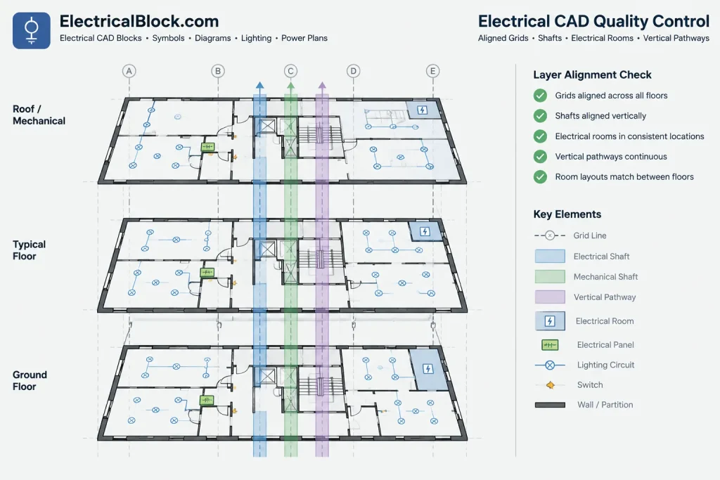
For multistory projects, compare common grids, shafts, risers, stairs, and major walls across floor files. Electrical risers and vertically aligned pathways are especially vulnerable when floor backgrounds use inconsistent origins.
5. Record Any Approved Transformation
If an offset or rotation is intentionally required, document it in a repeatable way. Do not leave the correction embedded only in one reference attachment. Future drafters should be able to reproduce the relationship and determine why it exists.
6. Lock Down the Reference Method
Once alignment is verified, use a consistent insertion procedure for subsequent updates. Protect reference placement from casual movement, and avoid binding or exploding backgrounds merely to make coordination easier.
Coordinate Checks for Different Electrical Drawing Types
| Drawing type | Primary alignment concern | Useful check |
|---|---|---|
| Interior lighting plan | Rooms, ceilings, grids, and fixture layout | Compare grid intersections, room boundaries, and ceiling reference features |
| Power plan | Walls, equipment, casework, and door locations | Review devices at several separated rooms and major equipment areas |
| Electrical site plan | Survey basis, property features, utilities, and building position | Confirm against the designated civil or survey control information |
| Roof electrical plan | Roof zones, equipment, curbs, and penetrations | Compare structural grids and coordinated roof equipment locations |
| Vertical pathway plan | Stacking of shafts, closets, sleeves, and risers | Overlay adjacent floors using common building controls |
| Equipment-room enlargement | Relationship to the parent floor plan | Verify that the enlarged view derives from the same coordinated geometry |
Avoid the “Looks Right” Correction
One of the most damaging coordinate practices is moving a background until it appears correct. Architectural plans may contain repeated bays, similar room arrangements, or multiple building wings. A file can therefore look aligned while being placed against the wrong reference feature.
Visual correction also conceals the original problem. The next background issue may be attached at its true coordinates, causing an apparent shift. Another drafter may copy the earlier manual adjustment, producing multiple competing placements within the same project.
If a background does not align, pause and classify the discrepancy. Is it a unit mismatch, an insertion-point issue, a rotation difference, a local-versus-survey coordinate relationship, or an actual design revision? Each cause requires a different response.
Managing Rotated Building Views
Rotated plans require particular care because model orientation and sheet orientation may not be the same. Where possible, keep discipline geometry aligned with the established project coordinates and use views or viewports to create readable sheet presentations. Rotating the entire electrical design independently can break overlays and complicate later coordination.
If the project intentionally uses separate orientations for different wings or areas, identify the boundaries and reference method clearly. Key plans, match lines, and directional references should agree with the displayed view. Labels and symbols may be adjusted for sheet readability without redefining the underlying project location.
Coordinate Quality Control Before File Exchange
Before issuing an electrical CAD file to another discipline, perform a coordinate-specific review:
- Confirm that electrical geometry has not been unintentionally moved from the governing background.
- Check for stray objects located far from the project that could affect drawing extents.
- Verify drawing units and the expected insertion method.
- Remove temporary copied backgrounds that could be mistaken for current source information.
- Identify any intentionally rotated or locally positioned views.
- Confirm that external references use the agreed project placement.
- Provide a simple control graphic or reference marker when required by the exchange plan.
- State whether the recipient is receiving project-coordinate geometry, a local working file, or a sheet-oriented export.
A recipient should not have to reverse-engineer the file’s location from plotted sheets. Clear exchange notes reduce the risk that another discipline will scale, rotate, or relocate the electrical information unnecessarily.
Responding to a Coordinate Change
A coordinate change should be treated as a project-wide coordination event, not an isolated background update. Determine whether the source geometry actually moved, the coordinate definition changed, or the file was merely exported differently.
Before modifying electrical geometry, preserve a comparison reference and consult the responsible discipline. Then assess affected plans, equipment layouts, site work, penetrations, enlarged views, and linked consultant files. Record the decision so that later issues do not restore an obsolete placement.
Build Coordinates Into the CAD Workflow
Reliable electrical CAD coordinates depend on repeatable documentation, not a clever one-time fix. Establish the governing basis early, test alignment at multiple control features, preserve the relationship during background updates, and communicate the coordinate method with every file exchange.
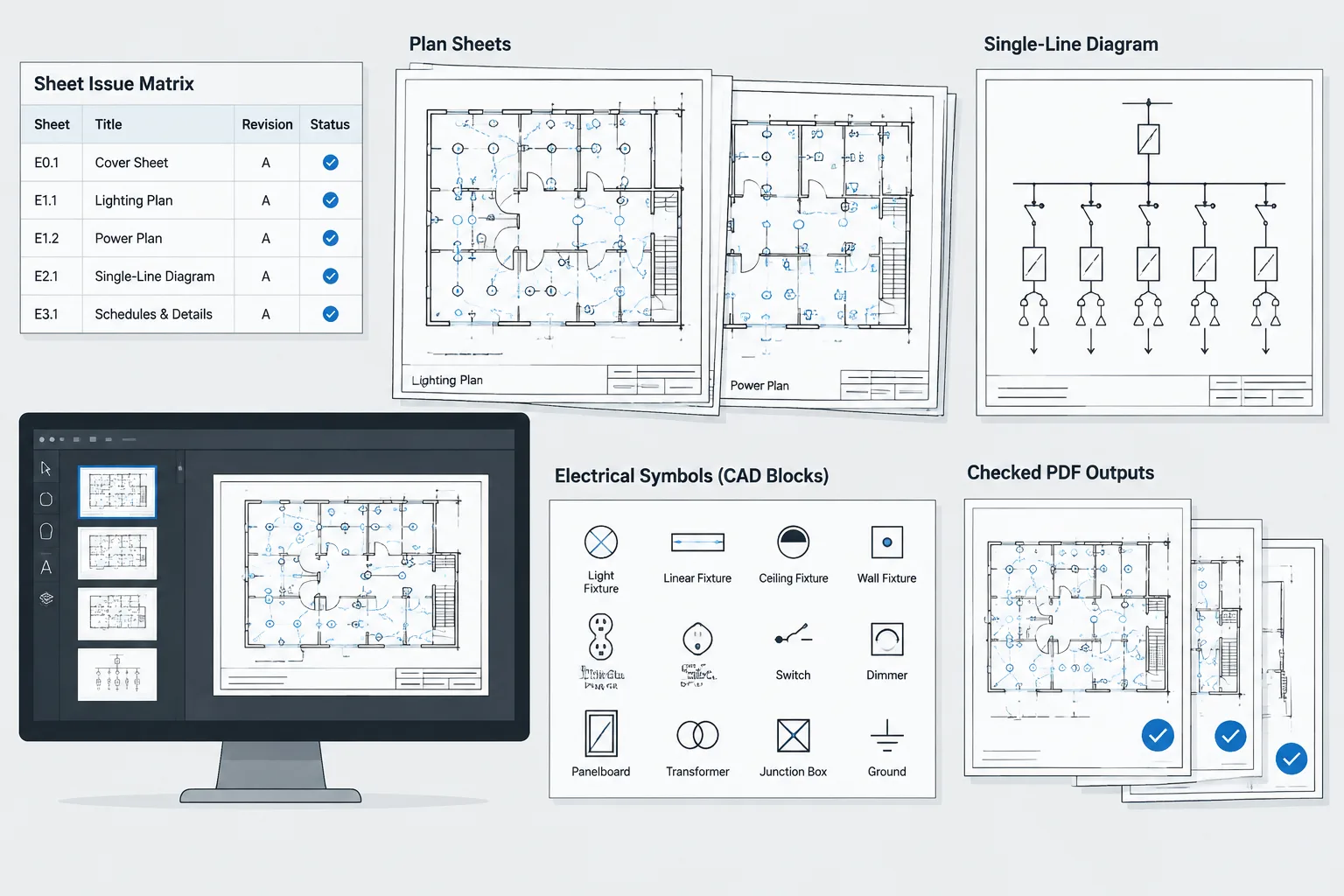
CAD blocks and symbols can be reused across many projects, but their project locations must always be verified against current coordinated information. A well-managed coordinate workflow lets those blocks remain useful drafting resources while keeping the assembled electrical plans aligned, reviewable, and dependable.
Separate Placement Errors From Design Changes
When an updated background no longer aligns, compare it with the previous coordinated issue before moving electrical content. A consistent displacement across the plan may indicate a changed insertion method or coordinate basis. A discrepancy limited to a room, wall, or equipment area is more likely to reflect a design revision. Differences that increase across the drawing may point to rotation, scale, or unit interpretation.
This classification helps the team direct the question to the appropriate source. It also prevents a genuine architectural or civil change from being hidden by repositioning the entire reference.
Use Control Features as Evidence
A good alignment review uses stable project features rather than temporary partitions, annotation, hatch boundaries, or equipment outlines that may change during design. The selected controls should be recognizable in the governing background and in the electrical working file.
- Plan control: Use agreed grids, building corners, cores, or designated site features.
- Orientation control: Confirm that project north, plan rotation, and sheet presentation have not been confused.
- Unit control: Verify how each file interprets drawing units before considering a scale correction.
- Issue control: Record which background issue was used for the comparison.
- Exchange control: State whether the delivered file retains project coordinates or uses an approved local relationship.
Document Exceptions Without Normalizing Them
Some received files may require an approved transformation because they were created under a different coordinate convention. Treat that condition as an exception rather than allowing it to become an undocumented office habit. Record the source file, reason, responsible discipline, and repeatable placement method.
Electrical geometry should remain traceable to the governing project basis. Reference attachment settings, view orientation, and sheet composition can support presentation needs without disguising where the design is located.
Coordinate Review at Handoff
A useful handoff note explains what the recipient should expect when attaching the electrical file. It should identify the coordinate basis, drawing units, orientation, governing reference, and any approved placement procedure. If a local working system is involved, the note should make that status explicit rather than implying that the file is already in the shared project system.
This information supports dependable overlays and makes later troubleshooting more objective. Instead of asking whether the plan merely looks correct, reviewers can determine whether it follows the documented project relationship.
Frequently Asked Questions
Why does an electrical background appear far from the drawing origin?
The file may be using a project, civil, or survey coordinate basis whose geometry is intentionally located away from the internal drawing origin. Confirm the documented coordinate method before relocating anything.
Should a background be moved into place if it does not align?
Not until the cause is known. Check units, orientation, insertion method, reference nesting, and the expected coordinate basis. Any necessary transformation should be approved and documented rather than estimated visually.
Can a rotated sheet plan still use the correct project coordinates?
Yes. Sheet presentation can be rotated through a view or viewport while model geometry remains on the established project basis. The team should distinguish a rotated view from geometry that has actually been transformed.
How can a drafter tell whether the problem is scale or position?
Compare stable features in widely separated areas. If the same displacement occurs throughout, placement may be the issue. If the discrepancy grows across the plan, investigate units, scale, rotation, or differences in the source geometry.
What should accompany an electrical CAD file exchange?
Include concise information about units, coordinate basis, orientation, governing background, reference procedure, and any approved offset or rotation. The recipient should be able to reproduce the intended placement without guessing.
Are CAD blocks affected by project coordinates?
The reusable block definition may remain unchanged, but each block instance must be placed against the current coordinated background. Copying project geometry between files can also carry an unintended coordinate relationship, so placement should be verified after transfer.








Leave a Reply
You must be logged in to post a comment.