
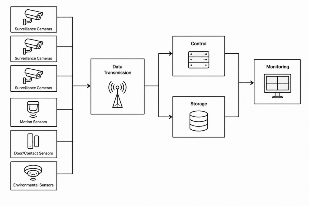
An active smart surveillance system DWG presents the functional relationships among surveillance devices, communication paths, control functions, data storage, and operator interfaces. Unlike an equipment layout, a block diagram focuses on how information moves through the system rather than where each device is physically installed.
This type of drawing can support design discussions, security-system documentation, academic diagrams, and coordination packages. The downloadable source content below should be retained with its original file information and download control.
Download a detailed Block Diagram of an Active Smart Surveillance System in DWG format, compatible with AutoCAD and other CAD platforms. This drawing illustrates the functional architecture of a smart surveillance setup, including cameras, sensors, data transmission units, control modules, storage, and monitoring interfaces. The diagram is cleanly layered, accurately labeled, and fully editable for integration into technical documentation, security plans, and academic projects. Ideal for engineers, security consultants, system designers, and students, this CAD block saves time, ensures clarity, and supports professional presentations of intelligent surveillance system designs.
Please log in or register to download this file.
How to Read the Surveillance System Block Diagram
Begin with the field devices, such as cameras and sensors, and follow the indicated signal path toward the data transmission and control portions of the system. Storage represents the recording or retention function, while monitoring interfaces show where operators or authorized users may observe system information.
Connections in a functional block diagram communicate relationships, not necessarily physical cable routes. A line between blocks may represent a data link, control path, or other logical connection. Project documentation should separately identify actual cabling, conduit, network infrastructure, power sources, and installation locations when those details are required.
Drawing Elements and Their Documentation Roles
- Cameras: Represent visual capture points within the surveillance architecture.
- Sensors: Indicate input devices that may provide event or condition information.
- Data transmission units: Show the functional path used to move information between system components.
- Control modules: Represent processing, coordination, or management functions.
- Storage: Identifies the part of the architecture associated with recorded data.
- Monitoring interfaces: Show the operator-facing or supervisory portion of the system.
Using the DWG in a CAD Documentation Workflow
After opening the file, review its layers, labels, line types, block definitions, and text styles before incorporating it into another drawing set. Confirm that imported content follows the destination project’s CAD standards and does not create duplicate layers or conflicting block names.
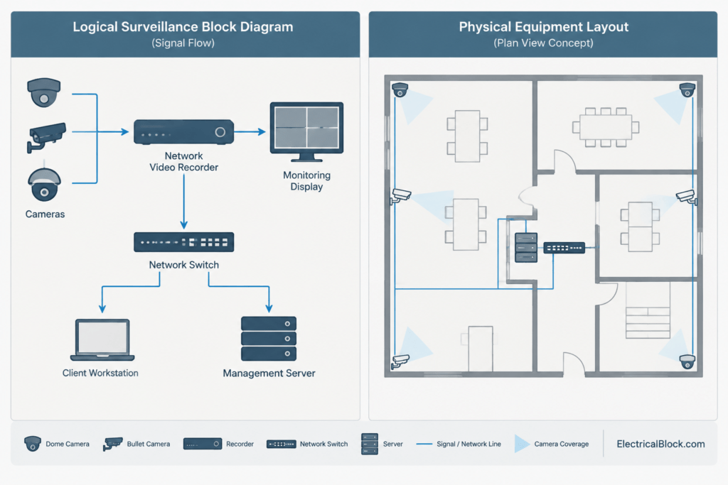
Keep functional architecture separate from physical planning. The block diagram can explain system logic, while an equipment layout can show device locations, a cable or conduit drawing can document pathways, and a legend can define symbols and abbreviations. A single-line-diagram concept may also help organize major connections, but its notation should not be assumed to replace detailed security-system documentation.

Editing and Quality-Control Considerations
- Preserve clear flow direction between capture, transmission, control, storage, and monitoring functions.
- Use consistent terminology across the block diagram, equipment schedules, legends, and plan annotations.
- Check that labels remain readable at the intended plotting scale.
- Distinguish logical communication links from physical wiring or conduit routes.
- Use revision notes when system relationships or component names change.
- Verify all project-specific selections, interfaces, and installation requirements with the responsible design professionals and applicable project criteria.
Related Drawing References
Useful companion topics include surveillance camera symbols, low-voltage legends, equipment layout drawings, cable and conduit drafting, network block diagrams, control-system diagrams, CAD layer organization, and annotation workflows. Reviewing these drawing types together helps prevent a functional diagram from being mistaken for a complete installation plan.
Frequently Asked Questions
What does this surveillance DWG represent?
It represents the functional architecture of an active smart surveillance system, including cameras, sensors, transmission units, control modules, storage, and monitoring interfaces.
Is a block diagram the same as a surveillance equipment layout?
No. A block diagram emphasizes functions and information flow. An equipment layout emphasizes physical placement, spatial coordination, and location references.
Can the diagram be edited for another drawing package?
The source describes the DWG as editable. Before reuse, inspect its layers, labels, blocks, and linework, then align them with the receiving project’s drafting conventions.
Does the drawing define cable routes and installation requirements?
Not necessarily. Functional connections should not be interpreted automatically as physical cable or conduit routes. Those details require dedicated project documentation and professional verification.
What should be checked before plotting the diagram?
Review text readability, line hierarchy, layer visibility, connection clarity, title information, abbreviations, and consistency with related legends and schedules.





Leave a Reply
You must be logged in to post a comment.