
A main electrical panel DWG block provides reusable CAD geometry for representing a primary distribution panel in electrical drawings. Before placing the block in a project, review its view type, insertion scale, layers, linework, and text so the graphic matches the conventions used throughout the drawing set.
The downloadable source content is preserved below. The accompanying guidance explains how to evaluate and document the block without assuming that its appearance, annotations, or configuration automatically matches a particular installation.
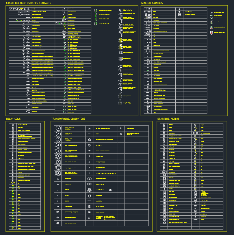
Download a high-quality DWG file of a Main Electrical Panel CAD Block, perfect for your electrical design projects. This detailed drawing is ideal for architects, engineers, and contractors who require precise representations of main electrical panels in their layouts. The file is fully compatible with AutoCAD and other CAD software, ensuring seamless integration into your schematics. Use this CAD Block to enhance your electrical plans, streamline project workflows, and comply with industry standards. Save time and improve accuracy by incorporating this ready-to-use Main Electrical Panel DWG file into your next project.
Please log in or register to download this file.
How a Main Electrical Panel Block Is Used
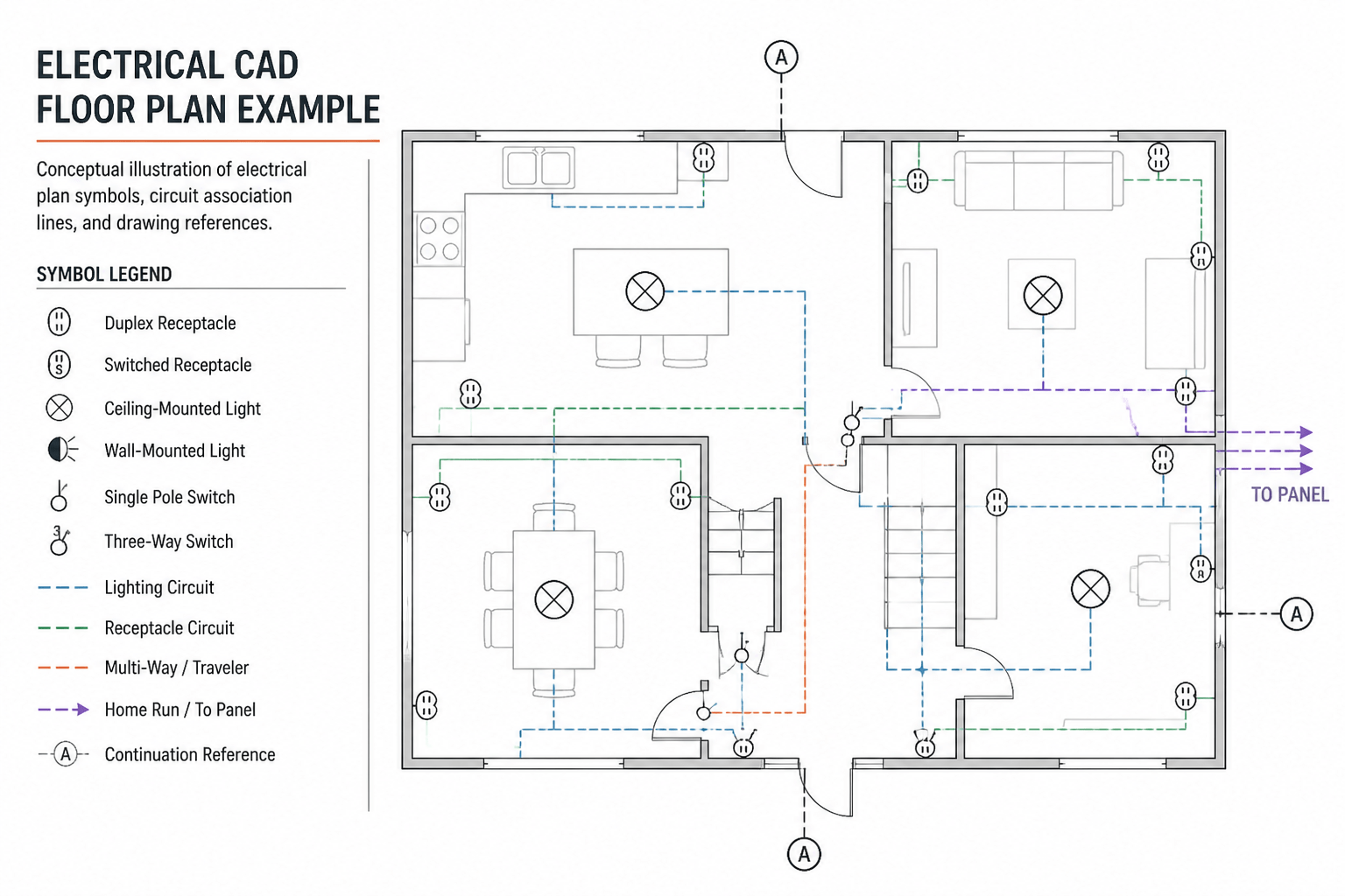
A panel block can help identify equipment location and function on an electrical plan or equipment layout. Depending on how the source drawing was created, the geometry may depict a plan symbol, elevation, enclosure outline, or another drafting representation. Open the file and inspect the actual view before assigning it a role in the project.
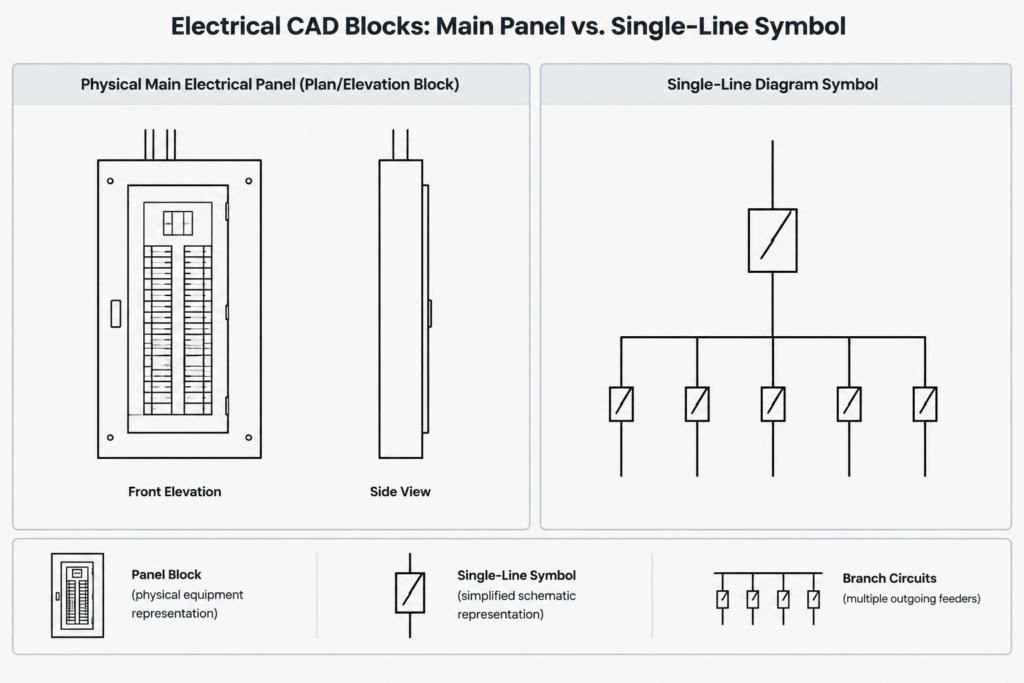
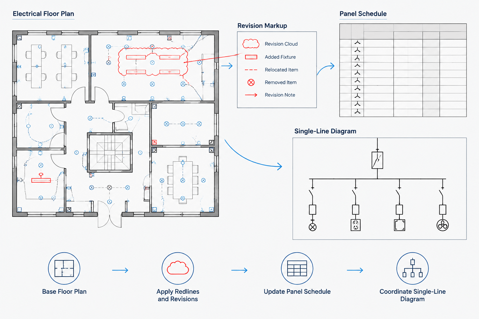
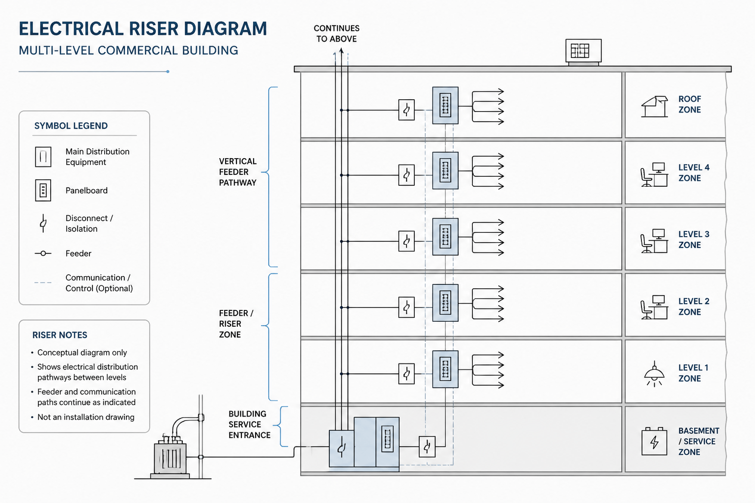
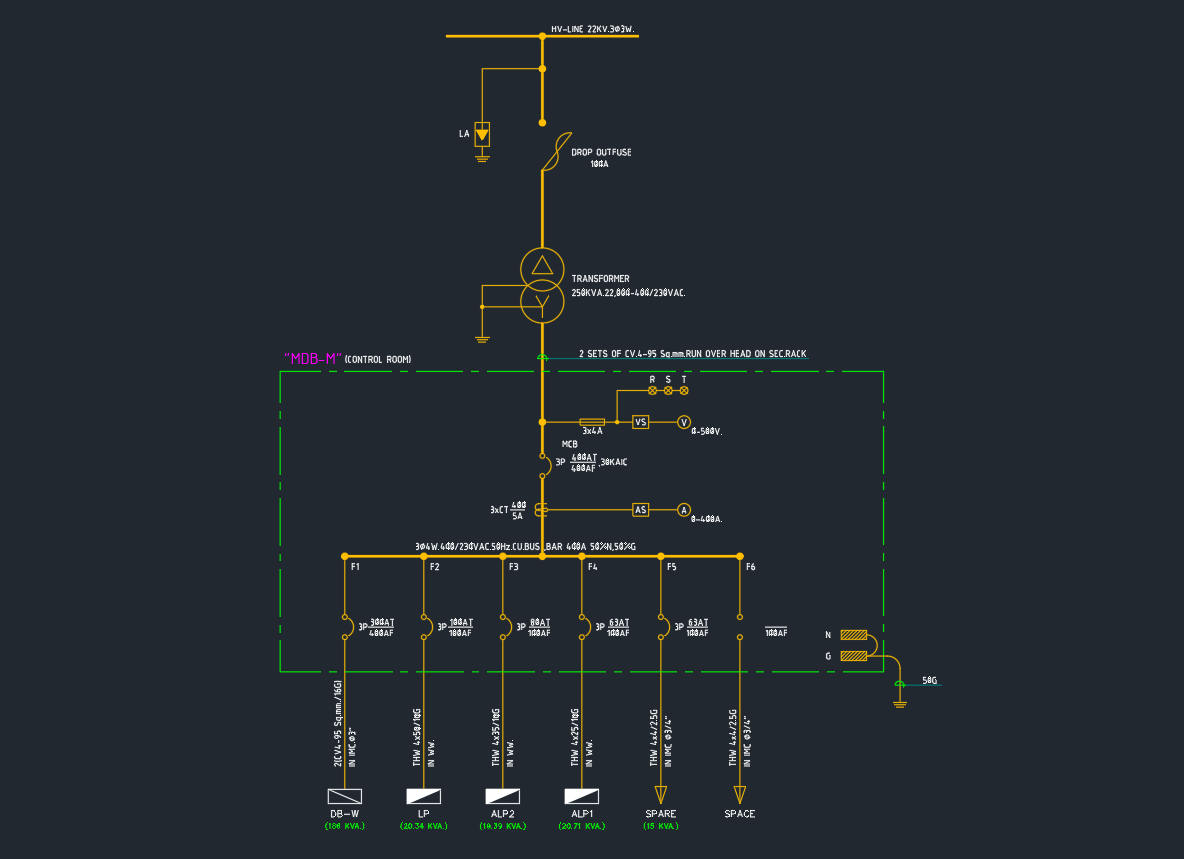
A physical equipment block should not be confused with the simplified panel symbol used in a single-line diagram. Layout drawings emphasize placement and coordination, while distribution diagrams communicate electrical relationships between sources, panels, feeders, and connected systems. A coordinated drawing set may use both representations, but each serves a different documentation purpose.
DWG Review Checklist
- Drawing units: Confirm the source units before scaling or inserting the geometry.
- View orientation: Determine whether the block is intended for a plan, elevation, detail, or diagram.
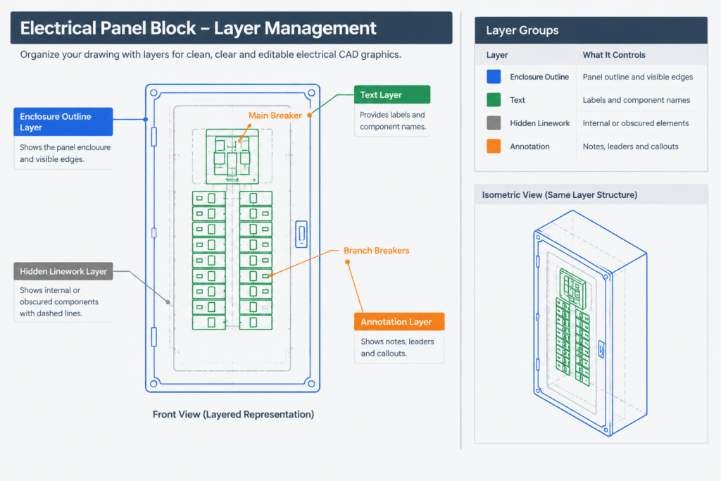
- Layers: Map imported objects to the project layer structure where appropriate.
- Linework: Check linetypes, lineweights, hatches, and plotting behavior.
- Text and attributes: Replace generic labels with verified project identifiers rather than embedding unconfirmed equipment data.
- Base point: Select a logical insertion point that supports consistent alignment and relocation.
- Geometry: Remove accidental duplicates or unrelated objects while preserving useful detail.
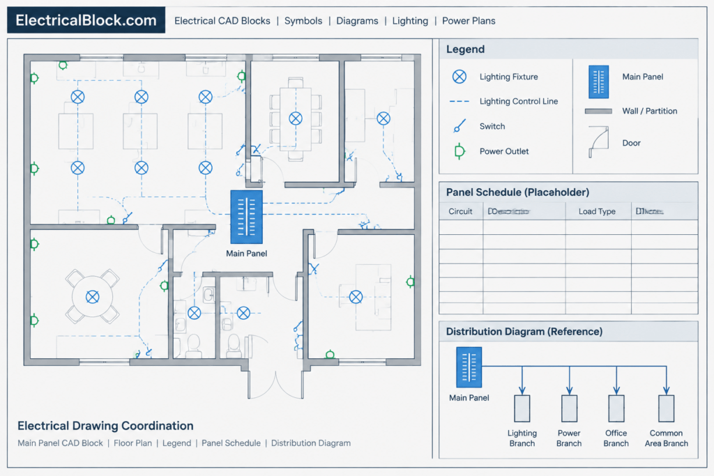
- Coordination: Compare the placed block with architectural backgrounds, equipment layouts, schedules, and distribution drawings.
Layer and Annotation Workflow
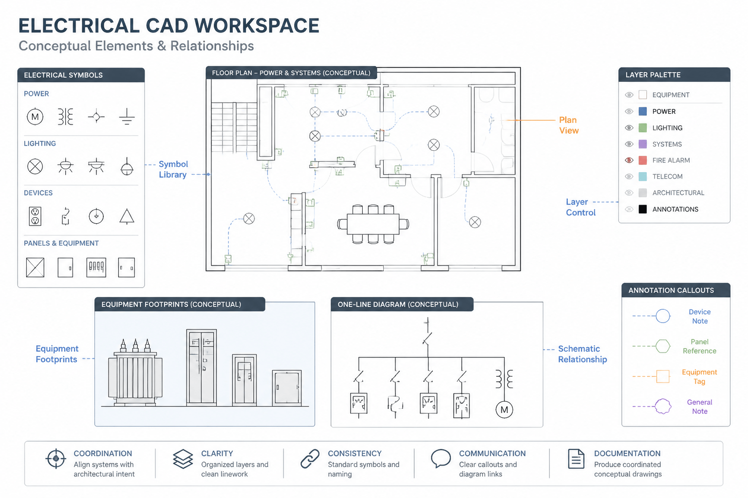
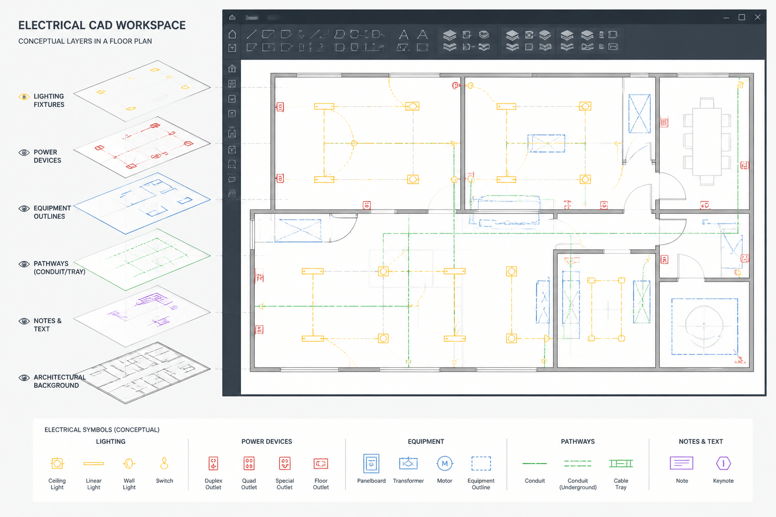
Reusable blocks are easier to manage when their objects follow a predictable layer strategy. Avoid leaving important geometry on unexplained imported layers. At the same time, do not force every object onto a single layer if separate layers are needed to control outlines, hidden information, text, or other drawing components.
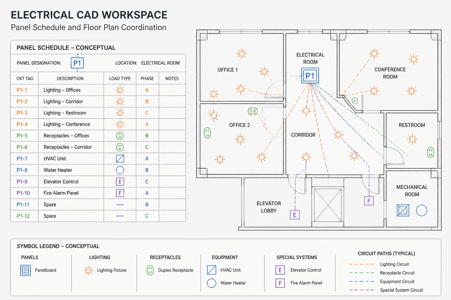
Keep project-specific information separate from generic geometry whenever practical. Panel tags, equipment names, circuit references, feeder notes, and keyed annotations should be based on verified design documents. This makes the same block easier to reuse while reducing conflicts between the graphic and the project schedule.
Related Drawing References
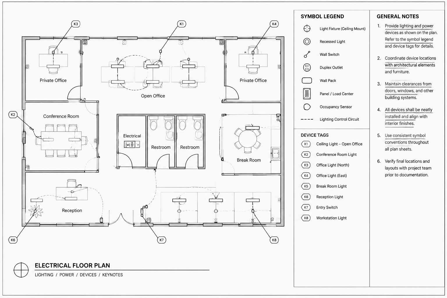
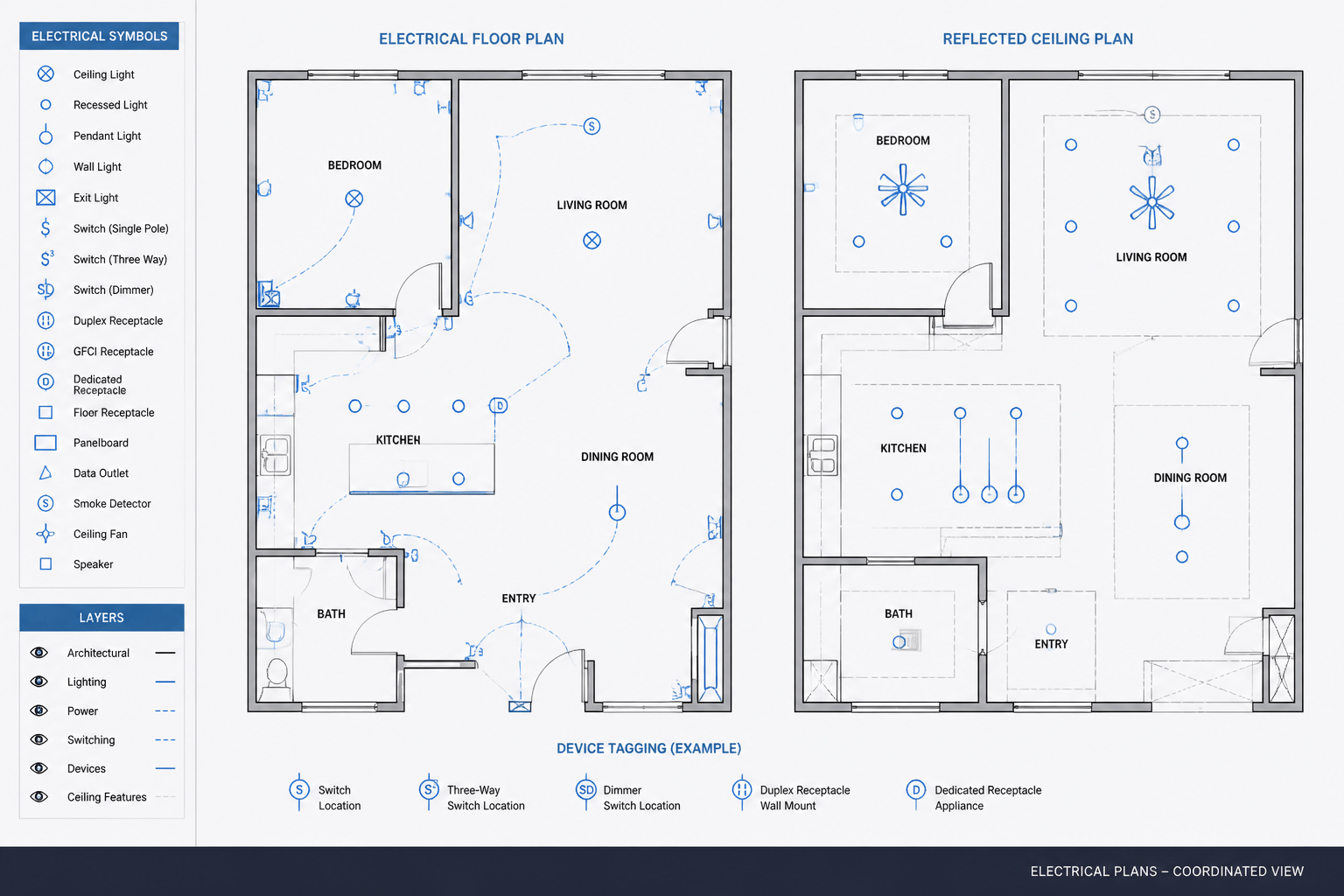
Users working with this block may also need references covering electrical panel symbols, power-plan drafting, single-line diagrams, panel schedules, equipment layouts, electrical legends, CAD layers, and annotation workflows. These topics clarify how a panel graphic fits into the larger drawing package rather than treating the block as a stand-alone design.
Important Verification Note
A CAD block is a drafting resource, not proof that a panel type, configuration, clearance, rating, or installation is suitable for a project. Confirm the drawing against approved equipment information, project requirements, and applicable professional review before issuing construction documents.
Frequently Asked Questions
What does the main electrical panel DWG block represent?
It represents a main electrical panel as CAD geometry. The exact view and level of detail should be confirmed by opening and inspecting the downloaded drawing.
Can the block be used in a single-line diagram?
Only if its graphic style is appropriate for that purpose. Single-line diagrams generally use simplified symbols and connections, while equipment blocks may be intended for plans, elevations, or layouts.
Should the block be scaled after insertion?
First compare the source drawing units with the destination file. Correct unit settings and insertion behavior are preferable to visually guessing at the required scale.
Can panel labels be edited?
Editable text or attributes may be revised when present. Use verified project identifiers and keep labels coordinated with schedules, diagrams, legends, and equipment references.
Does the DWG block define the required panel specifications?
No. The graphic alone does not establish ratings, internal configuration, installation requirements, or project suitability. Those details must come from verified design and equipment documentation.
Leave a Reply
You must be logged in to post a comment.