
A floor standing electrical enclosure DWG can help establish equipment location, orientation, and drawing context within an electrical room or equipment layout. The block on this page is intended as editable CAD reference geometry that can be incorporated into a broader documentation workflow.
Before placing the enclosure in a project drawing, review the file structure, units, visible geometry, and insertion point. The represented cabinet should also be coordinated with the project equipment schedule, architectural background, and applicable installation requirements.
Download a high-quality DWG file of a Floor Standing Electrical Enclosure CAD Block, perfect for your electrical design projects. This detailed CAD drawing provides accurate dimensions and clear component representation, making it ideal for architects, electrical engineers, and designers. The Floor Standing Electrical Enclosure is commonly used in industrial and commercial settings to house electrical equipment securely. Fully compatible with AutoCAD and other major CAD software, this DWG file ensures seamless integration into your project workflows. Enhance your electrical enclosure layouts with this reliable and easy-to-edit CAD Block.
Please log in or register to download this file.
Using the Enclosure Block in an Electrical Layout
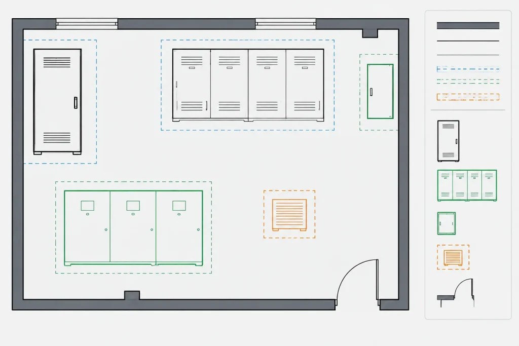
A floor-standing enclosure is generally shown as part of an equipment plan, room layout, elevation, or coordination drawing. Its graphic purpose is to communicate the enclosure footprint and position clearly. It should not be assumed to define internal devices, electrical ratings, construction details, or required access space unless those items are explicitly documented elsewhere in the project.
Recommended CAD Review
- Confirm drawing units: Compare the imported geometry with a known project reference before scaling or placing the block.
- Inspect the insertion point: Select a consistent reference location so the enclosure can be aligned accurately with walls, equipment rows, or layout grids.
- Review layers and properties: Reassign linework to project layers where needed and check color, linetype, and lineweight behavior.
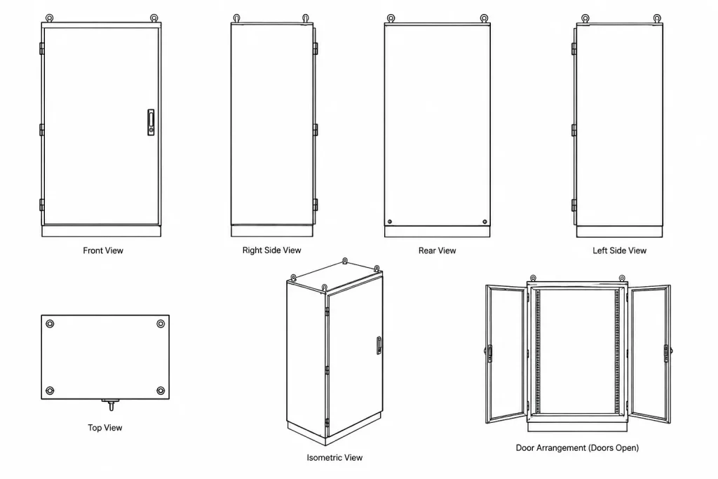
- Check the available views: Determine which enclosure view is represented and avoid using one view as a substitute for another without verification.
- Coordinate annotations: Use project-specific equipment tags, notes, and schedule references rather than embedding unverified technical information in the block.
- Verify placement: Compare the CAD representation with approved equipment information and the coordinated architectural and electrical backgrounds.
Relationship to Other Electrical Drawings
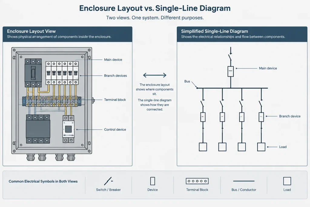
The enclosure block may be coordinated with power plans, electrical equipment layouts, panel and distribution drawings, cable or conduit routing plans, and drawing legends. A plan or elevation block communicates physical arrangement, while a single-line diagram communicates electrical relationships. Keeping these purposes separate makes the drawing set easier to review.
Documentation Limitations
A generic CAD block is a drafting aid, not a substitute for approved manufacturer information, project specifications, or professional design review. Confirm the enclosure configuration, orientation, access requirements, and associated equipment before relying on the geometry for construction, fabrication, procurement, or installation documentation.
Frequently Asked Questions
What is a floor standing electrical enclosure block used for?
It is commonly used to represent cabinet-style electrical equipment in plans, elevations, equipment-room layouts, and coordination drawings. The exact project meaning should be identified with an equipment tag, legend, or schedule reference.
Should the DWG be inserted at its original scale?
First verify the source drawing units against the destination file. Avoid assuming that imported geometry matches the project scale or unit convention without checking a known reference.
Can this block represent a specific enclosure model?
Only when its geometry and documented features have been checked against approved information for that model. A generic enclosure block should not be treated as manufacturer-specific by default.
Does the block define internal electrical components?
Not necessarily. The enclosure outline may represent only the external cabinet. Internal panels, controls, protective devices, terminals, and cable arrangements should be documented separately when required.
How should the block be labeled in a project drawing?
Apply the project equipment identifier and connect it to the appropriate legend, equipment schedule, or distribution documentation. Keep descriptive notes concise and avoid adding unverified ratings or specifications.
What should be checked before issuing the drawing?
Review units, scale, orientation, layers, linework, equipment identification, background coordination, and consistency with approved project documents.












Leave a Reply
You must be logged in to post a comment.