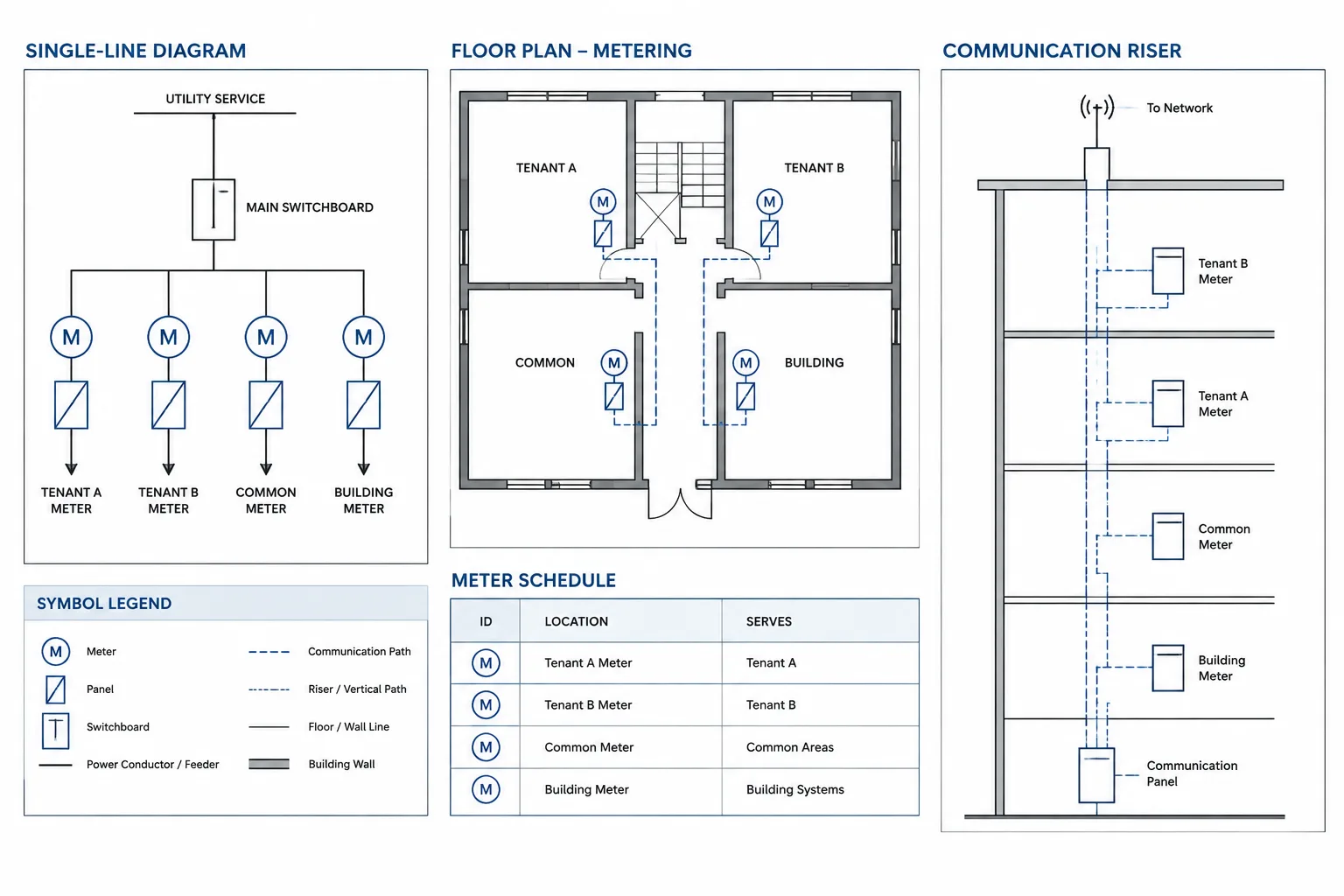
Electrical metering diagrams in CAD must connect system intent with equipment location and data reporting. A clear drawing package identifies the monitored electrical path, distinguishes utility metering from owner-installed submetering, and carries consistent device tags across single-lines, plans, risers, details, and schedules.
The following drafting workflow focuses on documentation clarity rather than manufacturer-specific design. Final arrangements, connection details, and utility interfaces should remain subject to project engineering, serving-utility requirements, and coordinated equipment information.
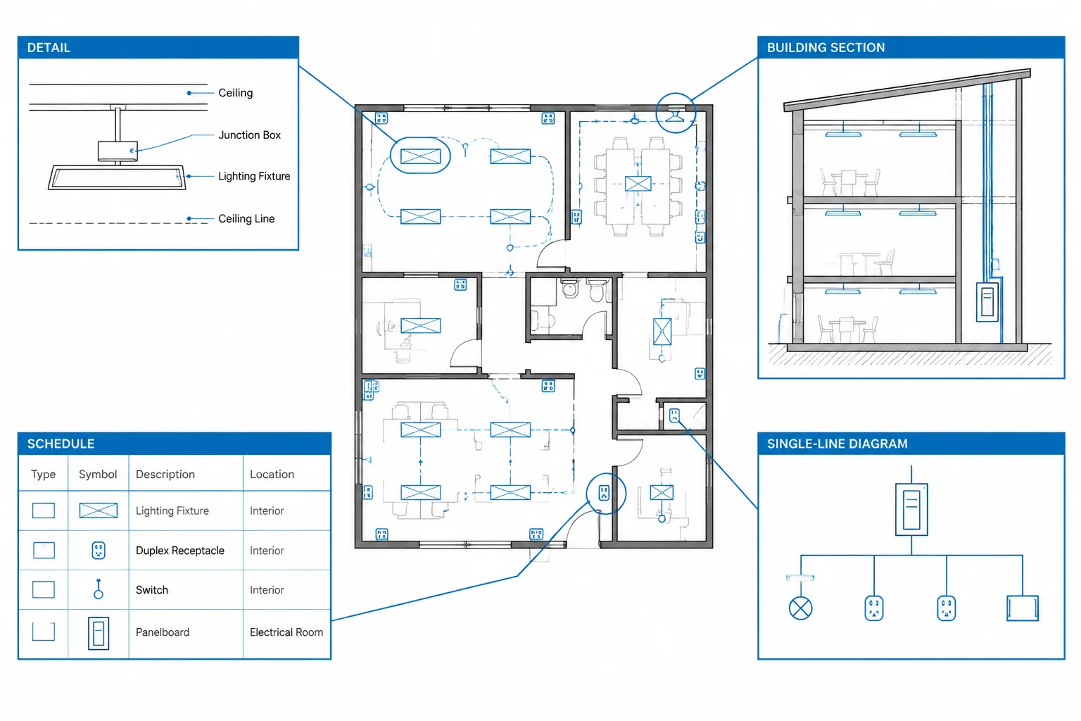
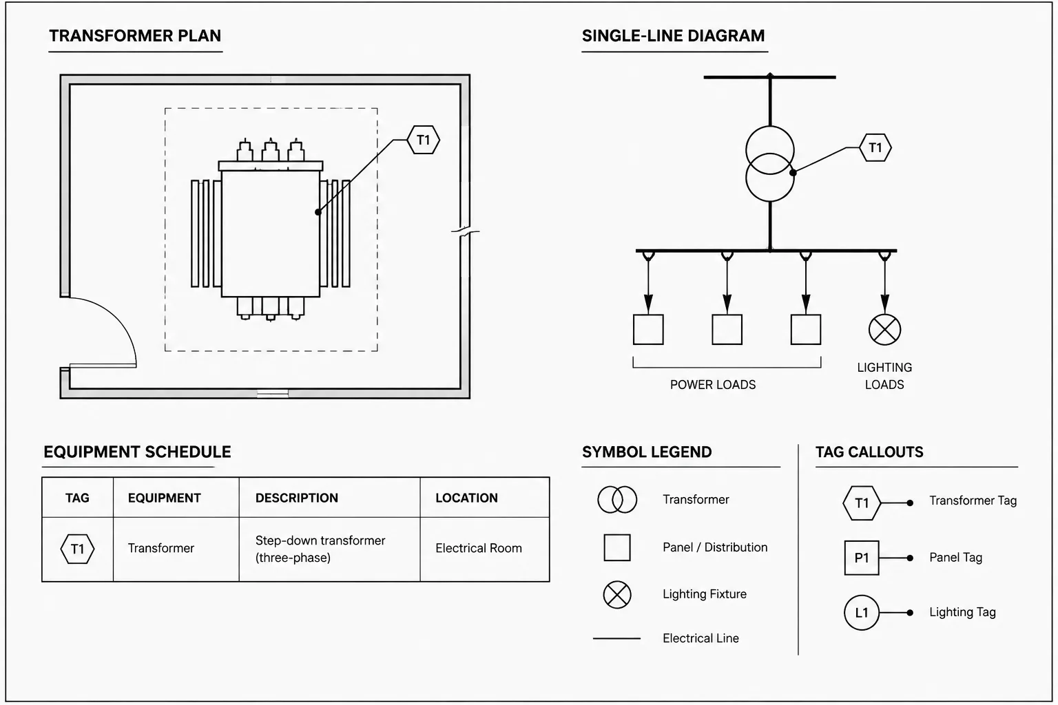
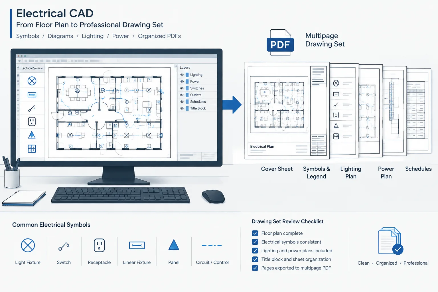
Electrical metering documentation often spans several drawing types. A single-line diagram explains where measurement occurs in the power distribution path, a floor plan shows the physical location of equipment, and a schedule records identifiers and monitored loads. Communication risers, equipment elevations, and control diagrams may add further information.
The drafting challenge is not simply placing a meter symbol. The drawings must distinguish utility metering from owner-installed submetering, identify what each device measures, and maintain consistent references between diagrams and physical layouts. This guide presents a documentation-focused workflow for creating an electrical metering diagram in CAD without assuming a particular manufacturer, utility arrangement, or project standard.
Begin with the purpose of the metering system
Before drafting symbols or circuit connections, establish why the measurement is being documented. Different purposes can require different drawing emphasis.
- Utility or revenue metering: Usually associated with the service arrangement and utility interface. Requirements and acceptable configurations must be confirmed with the serving utility and project engineer.
- Tenant or departmental submetering: Divides consumption among spaces, occupants, departments, or operational groups.
- Equipment monitoring: Records electrical use or operating information for selected panels, feeders, or major equipment.
- Energy management: Sends measured information to a monitoring platform, control system, or reporting interface.
- Temporary or verification metering: Documents a measurement point intended for a defined study or commissioning purpose.
Do not use a generic meter block to imply design decisions that have not been made. Mark uncertain arrangements as pending coordination and keep unverified connection details out of construction diagrams.
Decide which drawing carries each type of information
A readable metering package separates electrical relationships, physical location, and tabular data rather than forcing everything onto one crowded sheet.
| Drawing or schedule | Primary purpose | Typical metering information |
|---|---|---|
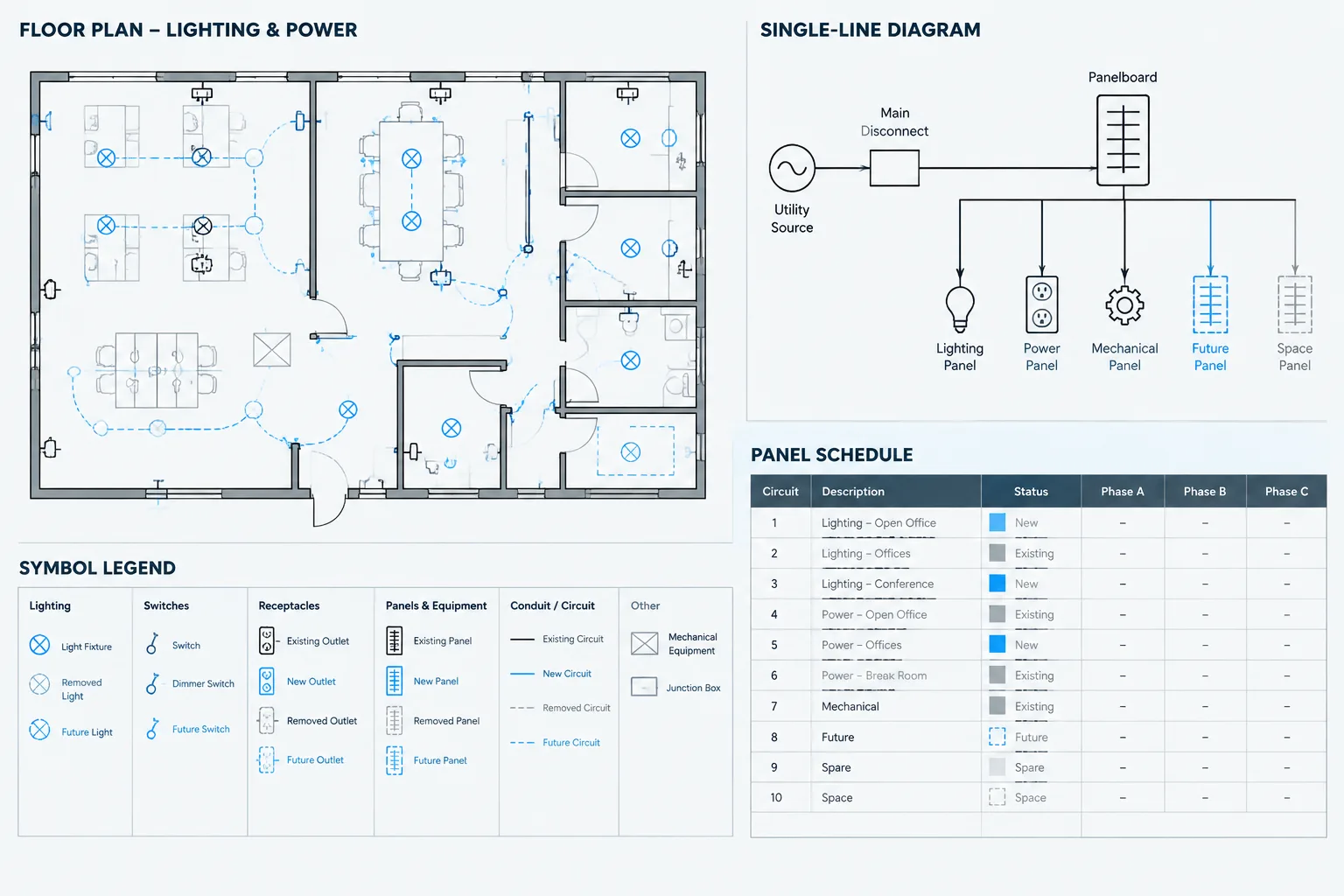
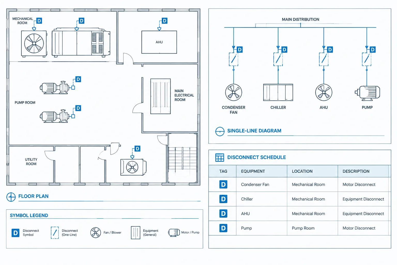
| Single-line diagram | Shows the power distribution relationship | Measurement point, associated feeder or bus, meter identifier, sensing arrangement, and source-load relationship |
| Electrical floor plan | Shows physical location | Meter cabinet, metering enclosure, local display, communication panel, and equipment tag |
| Riser diagram | Shows vertical or system relationships | Meters serving multiple floors, communication pathways, and links to remote monitoring equipment |
| Meter schedule | Organizes repeated data | Tag, service area, measured source, monitored load, location, and drawing references |
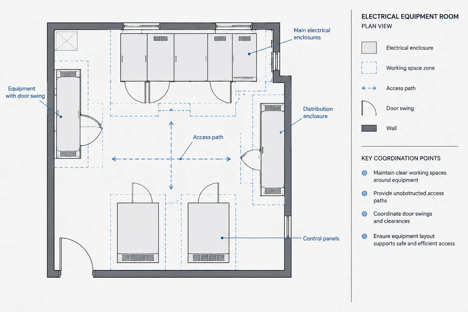
| Equipment elevation or detail | Clarifies arrangement | Relative enclosure position, device grouping, access orientation, and interfaces with adjacent equipment |
| Network or controls diagram | Explains data flow | Communication connections, gateways, controllers, and destination systems |
This division also helps reviewers. The single-line answers what is measured, while the plan answers where the equipment is located.
Build a clear metering symbol set
Metering symbols should be visually distinct from protective devices, switching devices, and general instrumentation. A project legend may include separate symbols for a complete meter, a sensing device, a local display, a communication gateway, and a metering enclosure.

Use symbol graphics to identify the device category, then use tags or adjacent text for project-specific identity. Avoid embedding long descriptions inside blocks. Excessive text makes diagrams harder to revise and can become unreadable when a drawing is reduced.
Use attributes for repeated information
An attributed CAD block can store fields such as:
- Meter tag
- Equipment or feeder reference
- Service area
- Location reference
- Schedule reference
- Status, such as existing, new, future, or to be removed
Attributes are most valuable when the same naming structure is used in schedules and diagrams. However, block data should not be treated as verified engineering data unless it has been checked against the design documents.
Separate graphics from connection assumptions
A symbol may indicate that metering is provided without defining every internal connection. Detailed sensing and terminal relationships should appear only when they are known and necessary for the document purpose. If another party will develop a manufacturer-specific wiring diagram, reference that responsibility rather than inventing a generic connection.
Place the measurement point correctly on the single-line
The position of a meter symbol on a single-line carries meaning. It should clearly relate to the conductor path, feeder, bus, or equipment being measured. Ambiguous placement can make one device appear to monitor an entire distribution section when it is intended to monitor only one outgoing feeder.
Draft the primary distribution path first. Add protective and switching devices as established by the design, then place the metering indication at the documented measurement point. Keep the symbol close enough to show association, but provide space for a tag and cross-reference.
If sensing elements are shown separately from the meter or display, use a consistent line convention to explain their relationship. Do not let a communication line resemble a power conductor. A dedicated layer, linetype, or clearly labeled connection can prevent confusion.
Coordinate the diagram with the physical plan
A diagram may show an electrical relationship that does not reveal where the actual components are installed. The meter, sensing equipment, display, and gateway may not occupy the same enclosure or even the same room.

On the floor plan, show only components that have a meaningful physical location. Give each item a tag matching the single-line or schedule. If a device is installed within another piece of equipment, the plan can identify the host equipment while an elevation or detail explains the internal arrangement.
Coordinate metering equipment with architectural backgrounds and other building systems. The drawings should account for wall-mounted cabinets, floor-standing equipment, pathways, and access areas without asserting clearances or installation requirements that have not been verified.
Distinguish power connections from data connections
Modern metering packages may include both electrical measurement relationships and communication networks. These should not be combined into one undifferentiated line system.
- Power distribution lines represent the conductors or bus being measured.
- Sensing relationships associate the measurement device with the monitored electrical path.
- Control or auxiliary connections support device operation where applicable.
- Communication links transmit information to gateways, servers, controls, or monitoring platforms.
Create a small line legend when multiple connection types appear on the same diagram. If the network becomes complex, place it on a separate metering communication riser and cross-reference the electrical single-line.
Create a meter schedule that adds useful information
A meter schedule should complement the drawings rather than repeat every nearby note. Useful columns may include the meter tag, monitored source, served area, physical location, associated panel or equipment, communication destination, and remarks.
Keep field names neutral until design requirements are confirmed. For example, a column labeled communication interface may be appropriate during coordination, while a manufacturer-specific protocol field could be premature.
Every scheduled meter should be traceable to at least one drawing. Conversely, each tagged meter on a diagram or plan should have a schedule entry unless the project intentionally uses a different documentation method.
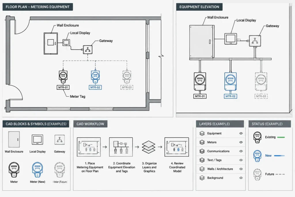
Use layers to control metering information
Metering content often benefits from separate CAD layers for symbols, tags, diagram connections, communication lines, and background equipment. Layer separation allows drafters to adjust visibility and plotting without exploding blocks or manually hiding objects.
A practical layer structure should follow the broader project CAD standard. The exact names matter less than consistent use. Avoid creating a unique layer for every meter unless the drawing workflow has a clear reason for that level of separation.
Document existing, new, and future devices carefully
Renovation projects may combine retained utility meters, new submeters, future provisions, and devices to be removed. Graphic status conventions must be clear in both the legend and the affected views.
Do not rely on color alone because printed sheets may be viewed in monochrome. Use an established combination of linework, text, tags, or status notes. A future meter should not look like an installed device, and an existing device should not automatically be interpreted as verified or reusable.
Perform a cross-drawing quality check
Before issuing the drawing set, review metering documentation as a connected system:
- Confirm that meter tags are unique and consistently formatted.
- Check that the measured source and monitored load are unambiguous.
- Compare single-line tags with floor plans, risers, schedules, and details.
- Verify that power, sensing, and communication lines are visually distinct.
- Confirm that existing, new, removed, and future statuses match across sheets.
- Check that references point to actual details or drawings.
- Remove unused symbols and outdated schedule rows.
- Review plotted output to ensure tags and connection lines remain legible.
- Flag utility, manufacturer, and controls requirements that still require confirmation.
A coordinated diagram is more valuable than a detailed block
A well-drawn meter symbol cannot compensate for unclear system relationships. Effective metering documentation connects three questions: what is being measured, where the equipment is located, and where the information goes.
By assigning these questions to the appropriate plans, single-lines, risers, and schedules, CAD users can produce drawings that are easier to review and maintain. Generic CAD blocks remain useful starting points, but their tags, attributes, connections, and status must always be adapted to verified project information.
Control information ownership during CAD development
Metering documents often combine information received from the electrical design team, utility, equipment suppliers, controls team, and architectural backgrounds. CAD objects should not make these inputs appear more certain than they are. Use coordination notes or a documented status field to distinguish confirmed information from placeholders and pending selections.
Establish which document controls each item. The single-line may govern the measured electrical path, the plan may govern the location tag, and the schedule may hold the shared description. When the same information appears in several places, revise every occurrence together or use coordinated attributes where the project workflow supports them.
Review both the objects and the complete drawing set
Object-level checks confirm that blocks, attributes, layers, and line conventions are correct. Sheet-level checks reveal broader problems such as conflicting tags, unclear source-to-load relationships, missing references, or communication lines that visually merge with power distribution graphics.
Revision review should also include deleted and relocated devices. Removing a meter symbol from one plan does not automatically remove its schedule row, riser reference, or network connection. A final plotted review is important because lineweights, screening, and background density can change the apparent hierarchy of the CAD file.
Prepare metering information for future revisions
Use stable identifiers instead of descriptions based only on room names or temporary drawing locations. Keep project-specific data in attributes or schedules where practical, while maintaining simple and reusable symbol geometry. This approach makes it easier to revise monitored areas, equipment associations, and device status without rebuilding the graphic library.
Before handoff, remove abandoned placeholders, identify unresolved coordination items, and confirm that the legend explains every symbol and connection style still visible in the issued views. The resulting documentation should communicate intent without implying unverified wiring, ratings, or equipment capabilities.
Frequently asked questions
What is the difference between a meter symbol and a metering connection?
A meter symbol identifies a device or metering function. A metering connection shows how that function relates to the monitored conductor path, sensing equipment, auxiliary components, or communication system. The symbol alone should not imply detailed wiring that has not been confirmed.
Should utility meters and owner-installed submeters use the same CAD block?
They may share a basic graphic style, but the legend, tag structure, attributes, or adjacent labels should make their roles clear. Utility interfaces require separate coordination and should not be represented as interchangeable with owner-installed monitoring.
When should communication information move to a separate riser?
A separate communication riser is helpful when data links, gateways, controllers, or remote destinations make the electrical single-line difficult to read. Cross-references should connect the communication view to the applicable meter tags and electrical equipment.
How should an unknown metering arrangement be shown?
Use a clearly identified placeholder or coordination note rather than drawing an assumed connection. Keep unsupported internal wiring and manufacturer-specific details out of the construction documents until verified information is available.
What should be checked when meter tags change?
Review every plan, single-line, riser, detail, schedule, equipment elevation, and network diagram that uses the tag. Also check callouts, references, block attributes, and status notes so the old identifier does not remain elsewhere in the set.
Leave a Reply
You must be logged in to post a comment.