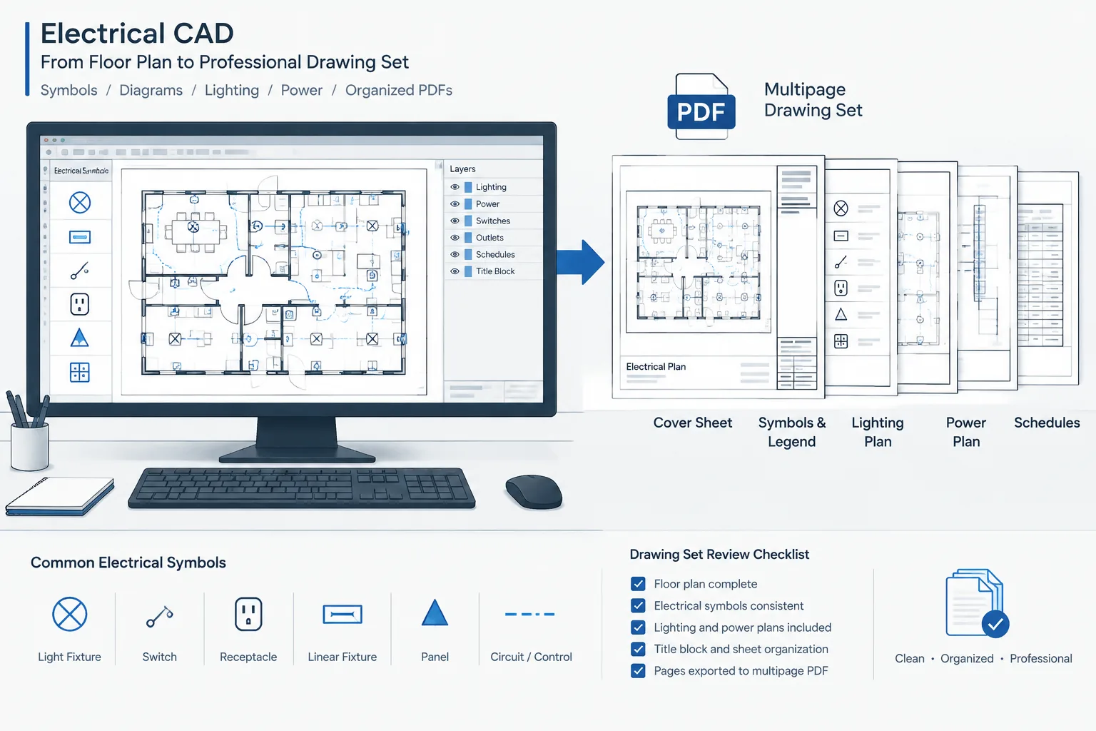
A drawing may look correct in CAD and still become difficult to use after it is published. Thin circuit lines can disappear, screened backgrounds can become too dark, symbols can fill in, and text may no longer be searchable. Sheet order, orientation, and revision information can also change during PDF assembly.
An effective electrical CAD to PDF workflow treats the PDF as a technical deliverable rather than a convenient printout. The objective is to preserve drawing hierarchy, readable annotations, reliable sheet navigation, and enough visual clarity for design review, coordination, estimating, and field reference.
Why the Published PDF Needs Its Own Quality Check
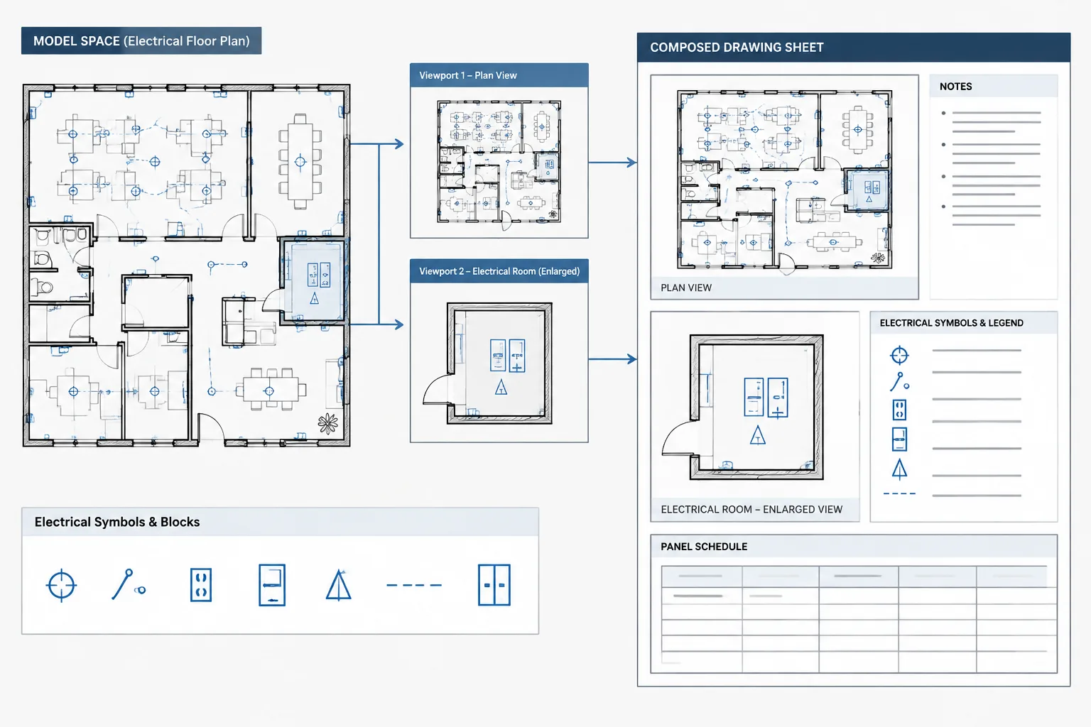
CAD files and PDFs serve different purposes. The CAD file contains model geometry, references, layers, layouts, and reusable objects. The PDF presents a controlled view of that information to people who may never open the source file.
Problems can appear during plotting even when the layouts are organized correctly. Common examples include:
- Electrical symbols merging into nearby architectural linework.
- Small text becoming broken, crowded, or difficult to search.
- Dashed or hidden lines appearing continuous at the published scale.
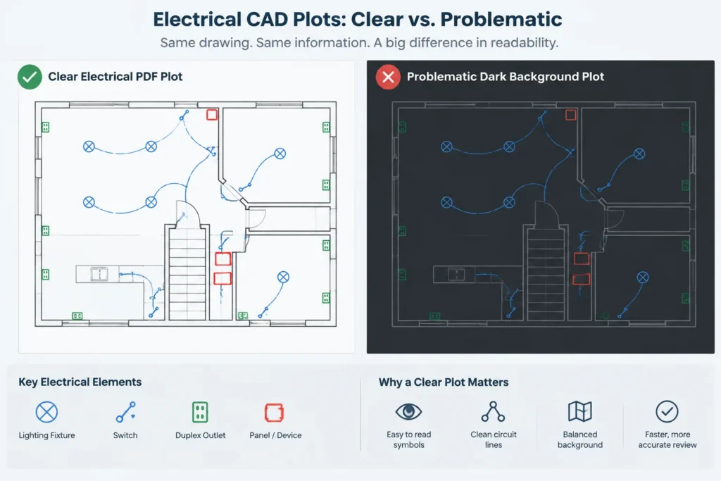
- Screened backgrounds printing darker than intended.
- Solid fills obscuring circuiting, tags, or equipment outlines.
- Unexpected color output in a set intended to be monochrome.
- Rotated, duplicated, missing, or incorrectly ordered sheets.
- Revision clouds or delta symbols disappearing from the issued file.
Reviewing only the CAD layouts does not catch every one of these issues. The final assembled PDF should be examined as an independent drawing package.
Prepare the CAD Sheets Before Plotting
Confirm the visible reference files
Check that architectural, structural, mechanical, civil, and other referenced backgrounds are loaded from the intended locations. A missing reference may be obvious in CAD, but an outdated reference can look complete while communicating incorrect coordination information.
Review reference visibility on representative sheets. Confirm that backgrounds are neither so prominent that they compete with electrical work nor so faint that walls, doors, ceilings, and equipment locations cannot be understood.
Inspect layers and viewport overrides
Layer conditions should be reviewed by layout, not only in model space. A layer may be visible in one viewport and intentionally hidden in another. Confirm that circuiting, device tags, match lines, detail references, and revision graphics appear wherever they are required.
Temporary drafting layers should not enter the published set. These may contain construction lines, internal notes, test geometry, imported markup, or alternate design studies. Use a repeatable layer-review process rather than relying on memory at issue time.
Check sheet-specific information
Before batch plotting, verify the title block information on every layout. Sheet numbers, titles, issue descriptions, dates, project identifiers, and revision entries should agree with the drawing index and the intended issue package.
Also check that north arrows, scale notes, key plans, match-line references, and continuation callouts remain correct after sheet layouts have been added, removed, or renamed.
Preserve Graphic Hierarchy in the PDF
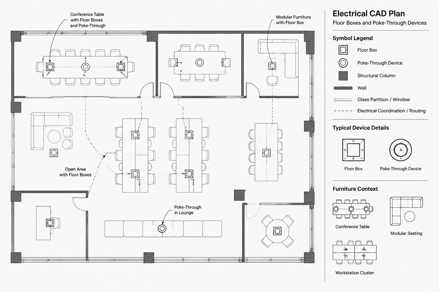
Electrical drawings depend on visual hierarchy. New electrical work should be distinguishable from backgrounds, annotations should remain legible, and major equipment should be easier to locate than secondary reference information.
| Drawing element | PDF review question |
|---|---|
| Electrical devices and equipment | Can symbols be identified without blending into walls, furniture, or ceiling grids? |
| Circuit and raceway lines | Are routes continuous and visible without overpowering device tags? |
| Existing or reference backgrounds | Do they provide context without competing with the electrical scope? |
| Text and tags | Are characters open, readable, and clearly associated with the correct object? |
| Hatches and solid fills | Do they preserve boundaries without covering nearby information? |
| Revision graphics | Are clouds and markers visible at normal review magnification? |
Do not judge linework only at extreme zoom levels. Review complete sheets at a comfortable on-screen size, then inspect dense areas more closely. A line that exists in the file may still be functionally invisible when someone reads the whole plan.
Keep Text Useful and Searchable
Searchable text makes large electrical sets easier to navigate. Reviewers can locate panel names, equipment tags, room references, detail titles, and keynotes without scanning every sheet manually.
Whenever the publishing method permits it, retain text as text instead of converting all sheet content into a flat image. After plotting, test searches for several known items from different sheets. Include a panel designation, a common device note, a sheet number, and a distinctive equipment tag.
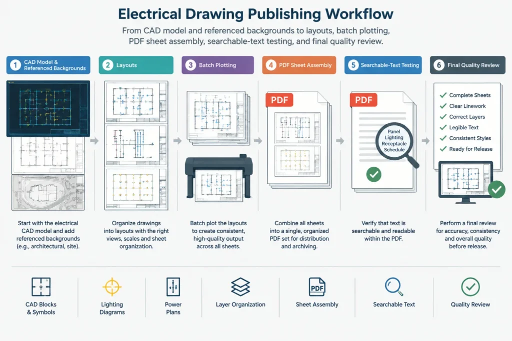
A failed search does not always mean the information is missing. Text may have been converted into geometry, rasterized, substituted, or divided into fragments. The visual result and the search result should therefore be checked separately.
Review Symbols, Fonts, and Special Characters
Electrical drawings often use compact symbols, stacked text, diameter marks, phase notation, arrows, and other specialized characters. Font substitution or plotting conversion can alter these items without producing an obvious error message.
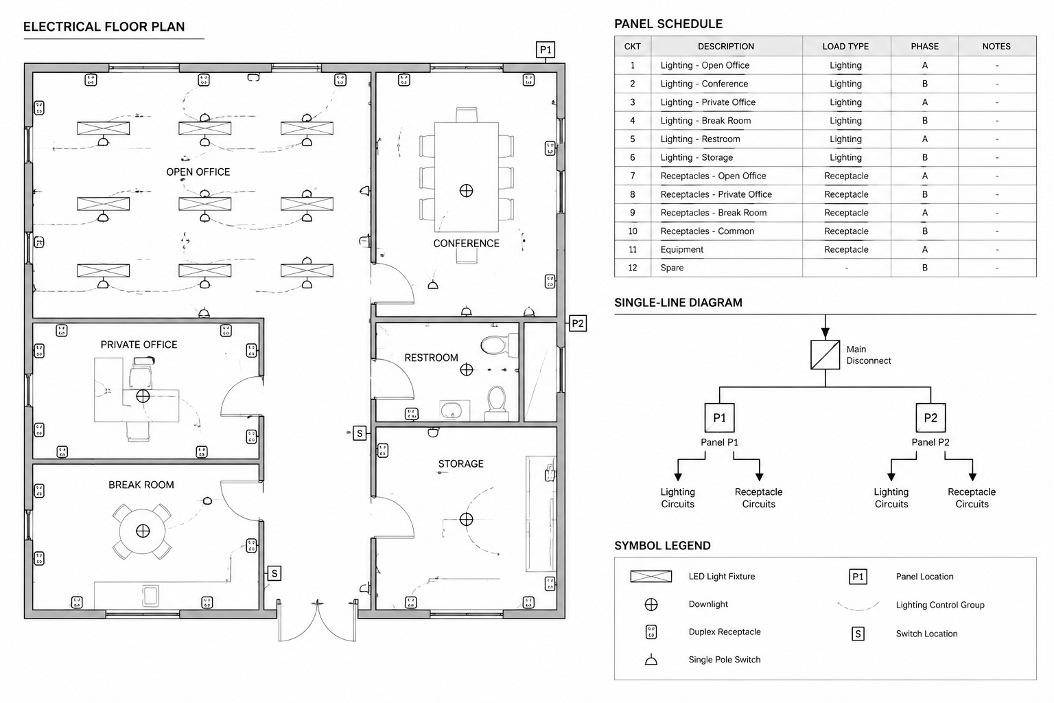
Inspect samples from legends, panel references, single-line diagrams, schedules, and detail sheets. Look for empty boxes, incorrect characters, changed spacing, filled symbol interiors, and labels that extend beyond their intended boundaries.
When a reusable CAD block contains text attributes, verify both the symbol geometry and its displayed values. A correctly plotted block outline does not guarantee that every attribute plotted correctly.
Assemble the Drawing Set Deliberately
Individual sheets may plot correctly while the combined package remains incomplete. Assemble sheets according to the project drawing index and confirm the sequence after combining files.
A practical assembly review includes:
- Comparing the PDF page count with the intended issue list.
- Checking the first and last sheet in each drawing group.
- Confirming that all pages use the intended orientation.
- Looking for duplicates created by repeated batch output.
- Verifying that superseded sheets are excluded.
- Confirming that addenda or revision sheets are placed as intended.
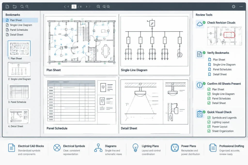
- Checking that bookmarks, if provided, match visible sheet numbers and titles.
PDF page labels, bookmarks, and sheet numbers are different navigation tools. If they are used, they should agree. A bookmark that opens the wrong page is more disruptive than having no bookmark at all.
Use a Representative-Sheet Review Strategy
Every final sheet should receive a basic visual review, but representative sheets can be used for deeper testing before the complete package is issued. Select sheets that challenge different parts of the publishing process, such as:
- A dense lighting or power plan with screened backgrounds.
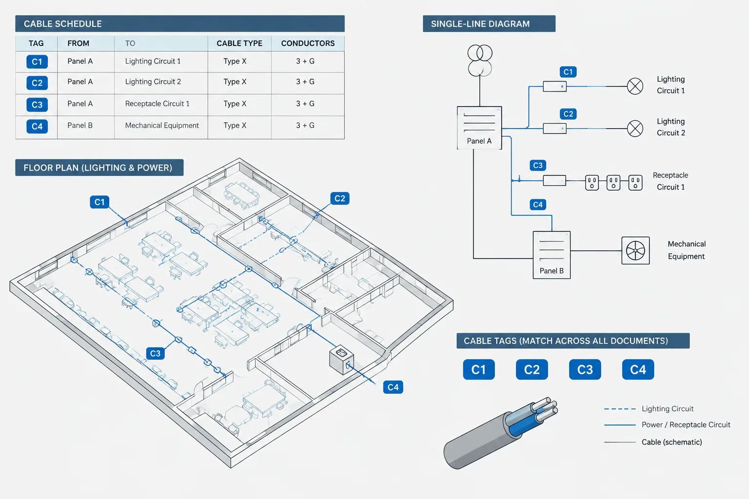
- A single-line diagram containing many symbols and line crossings.
- A schedule-heavy sheet with small text and repeated rows.
- A detail sheet containing hatches, fills, and leaders.
- A site or overall plan with long lines and multiple linetypes.
- A revised sheet containing clouds, markers, and updated title-block data.
If these sheets reveal plotting problems, correct the publishing setup and regenerate the package rather than editing the PDF to conceal source issues. Source corrections are more repeatable and are less likely to be lost during the next issue.
Separate Technical Markups from Issued Content
PDF review often produces comments, highlights, stamps, and sketch overlays. These are valuable during coordination, but they should not be confused with native drawing content.
Maintain a clear distinction between the review copy and the proposed issue copy. Accepted comments should be incorporated into the CAD source where appropriate, then verified in a newly generated PDF. Flattening review comments into an issue file can make temporary notes appear to be part of the design documents.
Final Electrical PDF Release Checklist
- Open the PDF on a system other than the one used to create it, when practical.
- Compare the sheet list, page count, and visible sheet numbers.
- Review full-sheet readability and several dense drawing areas.
- Test searches for tags, notes, panel names, and sheet identifiers.
- Check symbols and special characters for substitution or fill problems.
- Verify that backgrounds, hatches, and screened linework remain balanced.
- Confirm that current revision information appears on the required sheets.
- Check bookmarks or other navigation aids against the actual pages.
- Verify that no internal comments, temporary layers, or review overlays remain.
- Archive the issued PDF together with the corresponding source-file issue state according to the project documentation procedure.
A PDF Is Part of the Electrical Documentation System
The most useful electrical PDF is not merely a visual copy of a CAD layout. It is a controlled communication package that preserves scope, hierarchy, references, and navigation for users with different needs.
By checking source layers, plotting behavior, searchable text, symbol integrity, page assembly, and revision status, a drafting team can make the published set more reliable. The result is easier to review, easier to coordinate, and less likely to create questions caused by the document itself rather than the electrical design.
Leave a Reply
You must be logged in to post a comment.