
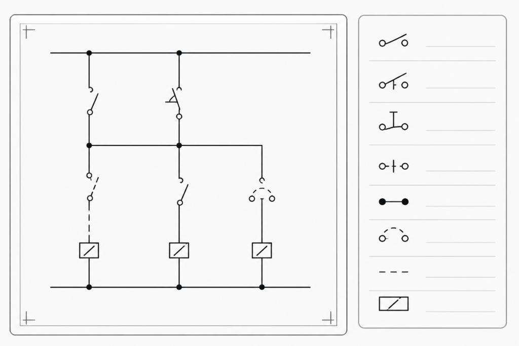
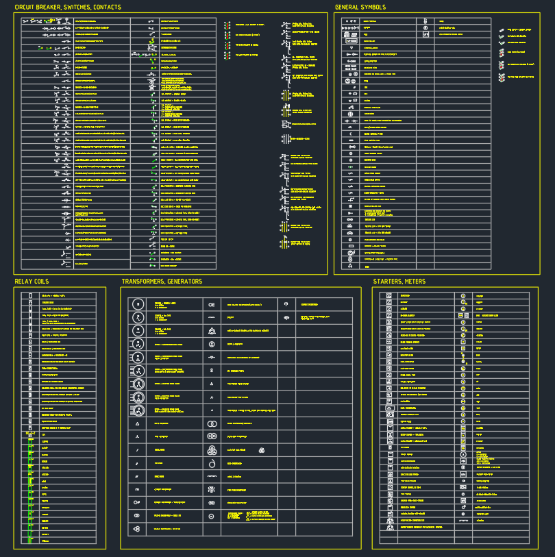
Clear electrical drawings depend on symbols that are easy to identify, consistently placed, and coordinated with the project legend. The Switches Contacts Symbols DWG collection provides reusable CAD content for schematic and electrical drafting workflows.
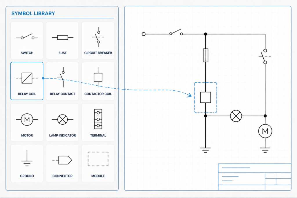
Use the downloadable block set as a starting point for organizing switch and contact representations in AutoCAD-compatible drawings. Always compare inserted symbols with the project’s approved legend, drafting conventions, and design documentation before issuing a drawing.
Discover our comprehensive DWG file featuring a collection of Switches Contacts Symbols, ideal for electrical and electronic schematic designs. This CAD Block set includes a variety of standardized symbols for switches and contacts, streamlining your drafting and design process. Perfect for engineers, electricians, and designers, these symbols are meticulously crafted for clarity and accuracy. The DWG file ensures seamless compatibility with AutoCAD and other leading CAD software, making integration into your projects effortless. Enhance your electrical plans with these professional Switches Contacts Symbols today!
Please log in or register to download this file.
How to use switches and contact symbols in CAD drawings
Switch and contact symbols communicate the intended function of a device without requiring every component to be drawn pictorially. Their value comes from consistent graphic language: the symbol should remain legible at the drawing scale, align with related conductors, and match the terminology used in schedules and notes.
Coordinate symbols with the electrical legend
Before using a block in a project, review its appearance against the drawing legend and office CAD standards. Different disciplines, manufacturers, and project teams may use variations in symbol presentation. The legend remains the controlling reference for interpreting the finished drawing.
Organize blocks for schematic drafting
- Place symbols on the appropriate drawing layer and keep their insertion orientation consistent.
- Use clear spacing so contacts, conductors, labels, and connection points can be read without confusion.
- Coordinate device tags and references with the associated equipment, panel, or control documentation.
- Check that the symbol remains readable after plotting, exporting, or opening the drawing in another CAD application.
Related electrical CAD documentation
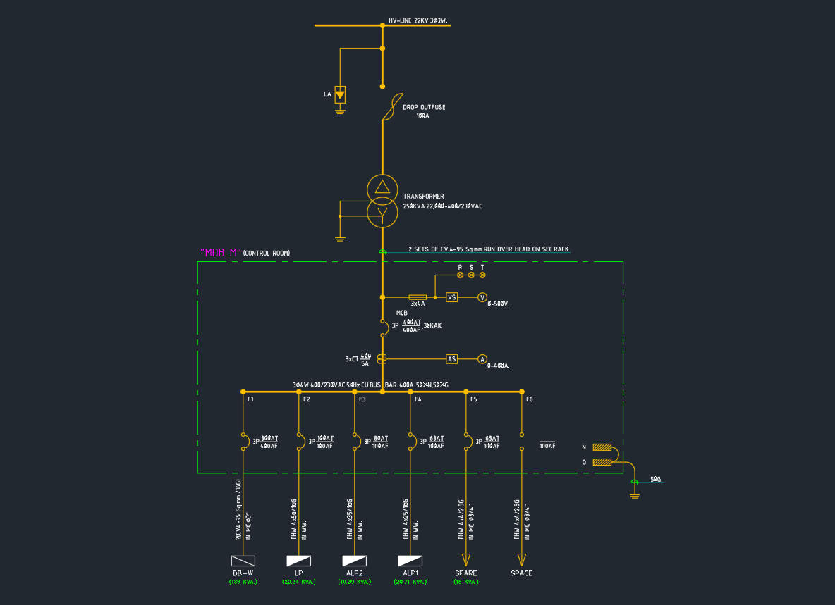
Switch and contact symbols commonly appear alongside electrical legends, schematic diagrams, panel documentation, single-line diagrams, lighting plans, power plans, and equipment layouts. Reviewing these related drawing elements together helps maintain consistent terminology and reduces coordination errors between plan views and schematic information.
What to verify before issuing a drawing
CAD blocks are drafting resources, not a substitute for project engineering review. Confirm the symbol identity, contact relationship, device reference, conductor connections, and applicable project conventions before the drawing is released. The downloadable DWG should be checked in the target CAD environment so that linework, layers, attributes, and block behavior remain suitable for the intended documentation workflow.
Frequently asked questions
What is included in the Switches Contacts Symbols DWG?
The source content describes a collection of CAD symbols for switches and contacts used in electrical and electronic schematic designs. Review the file itself to confirm the exact symbol inventory and drawing organization.
Can the DWG be used with AutoCAD?
The source content identifies the file as compatible with AutoCAD and other leading CAD software. Open and review the file in the target application before incorporating it into a project drawing.
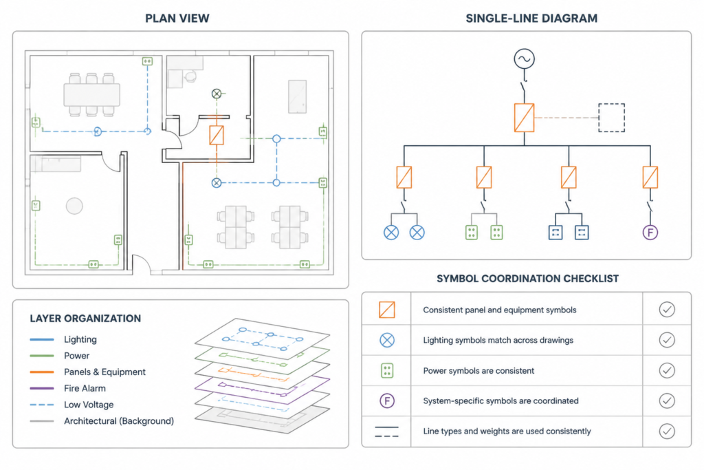
Are these symbols a replacement for an electrical legend?
No. The blocks support drafting, while the project legend and applicable design documentation define how symbols are interpreted for a specific drawing set.
Where can these symbols be used?
They can support schematic and electrical drafting workflows involving switches and contacts. Their final use should be coordinated with the project’s drawing standards, device references, and engineering review process.
Should the symbols be edited after insertion?
Edits may be appropriate when required by the project CAD standard, but preserve clarity and coordination with the legend. Verify any modified block before using it in issued documentation.
Leave a Reply
You must be logged in to post a comment.