
Voltage Nodes Symbols DWG supports clear electrical schematic drafting by providing reusable CAD representations for voltage node references. Use the downloadable block as part of a consistent symbol library, while checking each symbol against the project legend and drafting conventions.
This resource is intended for engineers, architects, CAD designers, students, and documentation teams working with electrical layouts, circuit diagrams, and related drawing packages. It can help reduce repetitive drafting and improve consistency across schematic documentation without replacing engineering review.
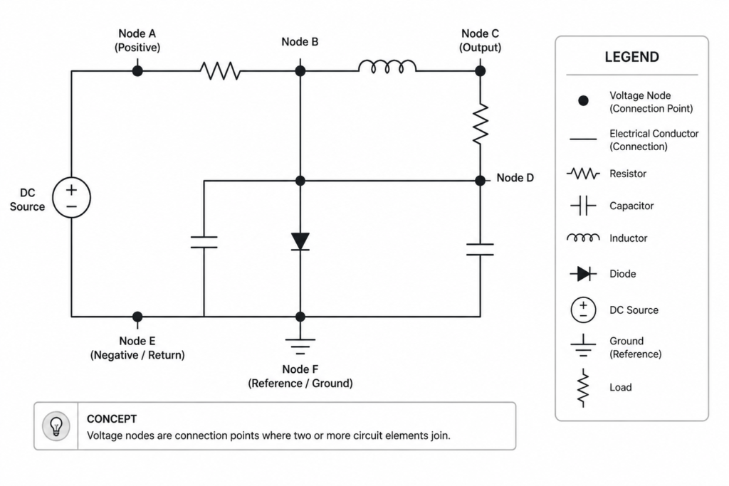
Download a high-quality DWG file featuring Voltage Nodes Symbols, essential for electrical schematic diagrams and circuit design projects. This CAD Block provides precise and standardized voltage node representations, making it ideal for engineers, architects, and CAD designers working on electrical layouts. The Voltage Nodes Symbols DWG file is fully compatible with AutoCAD and other popular CAD software, ensuring easy integration into your existing projects. Enhance your electrical drawings with accurate and professional symbols, streamlining the drafting process and improving documentation quality for construction or maintenance purposes. Perfect for both educational and professional use.
Please log in or register to download this file.
How voltage node symbols support schematic drafting
A voltage node symbol identifies a connection point or named electrical reference within a schematic. In a well-organized drawing, node symbols help readers follow relationships between circuit elements without relying on long connection paths or crowded linework. The exact meaning of a symbol should always be confirmed by the drawing legend, notes, and project standards.
Using the DWG in an AutoCAD workflow
- Review the block first: Open the file in a controlled drawing environment and confirm that the geometry, insertion behavior, layers, and visible labels suit the project.
- Match the drawing convention: Use the same text style, lineweight approach, orientation, and annotation practice applied to the rest of the schematic set.
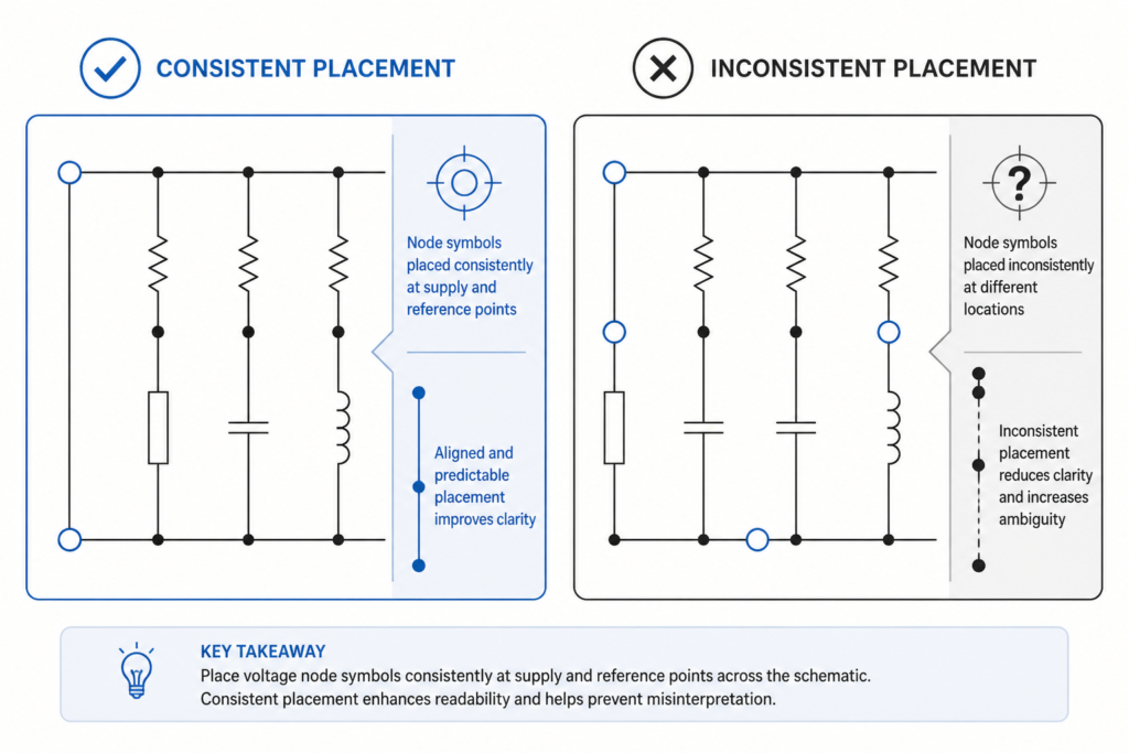
- Keep references consistent: Apply node symbols consistently across related sheets so that electrical connections and named references remain easy to trace.
- Coordinate with the legend: Confirm that the selected symbol has an unambiguous definition in the electrical legend or project notes.
- Check before issue: Review symbol placement, overlap, readability, and coordination with circuit lines, equipment references, and other drawing content.
Reference checklist
- Resource type: Voltage node symbol CAD block
- File format: DWG
- Primary drafting use: Electrical schematics and circuit documentation
- Software context: AutoCAD and other compatible CAD applications
- Coordination priority: Project legend, naming convention, layers, and annotation standards
- Review responsibility: A qualified design or documentation professional should verify the drawing before formal use
Related electrical CAD documentation
Voltage node symbols are most useful when coordinated with electrical legends, schematic symbols, single-line diagram graphics, panel documentation, and circuit reference conventions. Keeping these resources organized as one symbol and documentation system can make design intent easier to review and maintain.
Frequently asked questions
What is included in this Voltage Nodes Symbols DWG?
The resource is a DWG file featuring voltage node symbols for use in electrical schematic and circuit documentation workflows.

Can the file be used with AutoCAD?
Yes. The source description identifies the file as compatible with AutoCAD and other popular CAD software. Confirm compatibility with the specific application and project template before deployment.
Where should voltage node symbols be placed?
Place them where the project schematic convention requires a voltage node or named electrical reference. Always coordinate placement with circuit linework, labels, and the drawing legend.
Do these symbols replace an electrical design review?
No. A CAD block provides drafting geometry only. A qualified professional must verify the symbol meaning, connectivity, labeling, and overall design documentation.
Can the symbols be edited in a project drawing?
They can generally be incorporated into a compatible CAD workflow, but users should review block behavior, layers, attributes, and annotation settings before making project-wide changes.












Leave a Reply
You must be logged in to post a comment.