
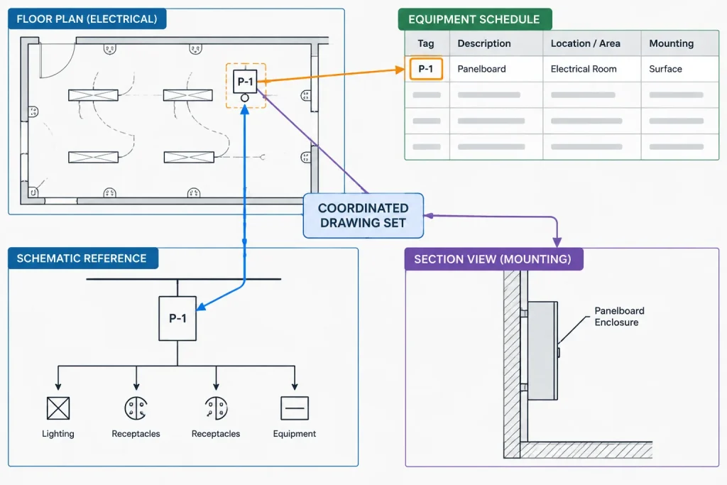
Junction and pull box documentation is most useful when each symbol participates in a coordinated drawing system. The plan establishes location and route relationships, while tags, schedules, diagrams, and details explain the enclosure’s identity and design intent. This guide focuses on building that relationship clearly in CAD without placing unsupported project data inside a generic block.
Junction and pull boxes can appear deceptively simple on an electrical plan. A small square or rectangle may represent an enclosure that connects several raceways, provides access to conductors, supports a change in route, or contains project-defined splices and terminations. If the symbol is not coordinated with tags, routes, elevations, and details, the drawing leaves critical interpretation to the reader.
Effective junction and pull box drawings in CAD do more than mark approximate locations. They establish a traceable relationship between the plan symbol, connected raceways, enclosure identification, installation context, and supporting documentation. The objective is not to place every construction decision on the floor plan. It is to give each drawing view the information it can communicate most clearly.
Junction box and pull box terminology
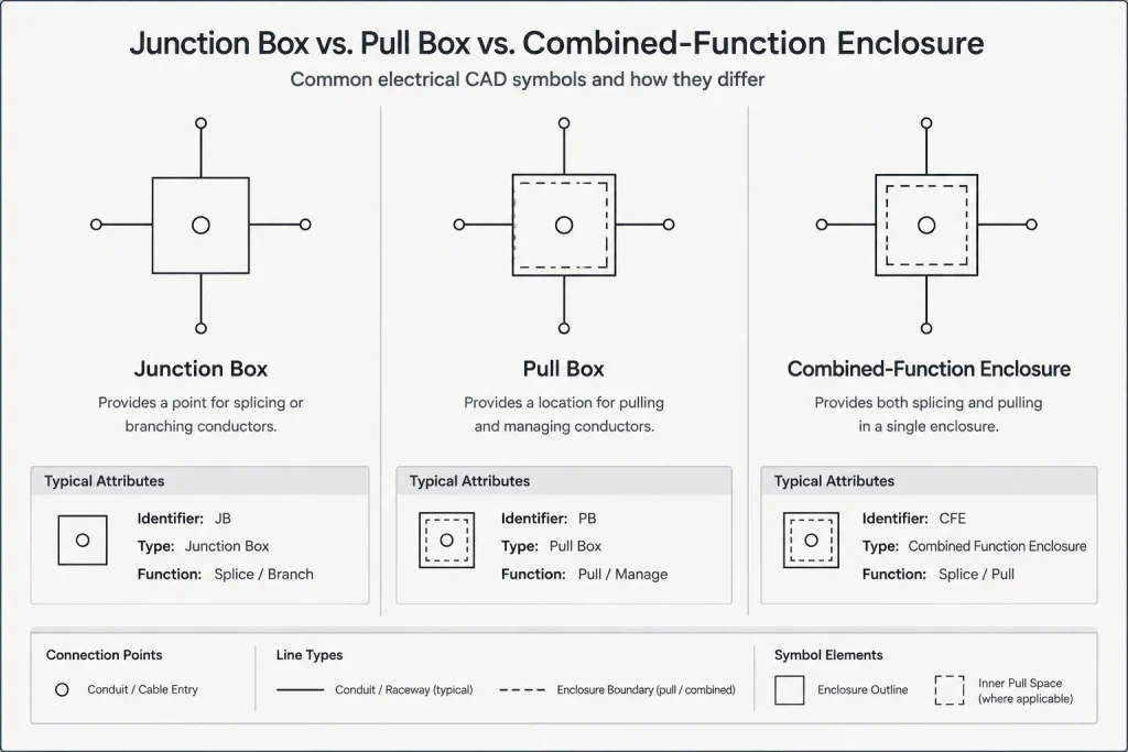
The terms junction box and pull box are sometimes used loosely in project documentation, but they can describe different intended functions. A junction box may provide an accessible location for conductor connections, branching, or transitions. A pull box generally provides access that helps divide or manage a raceway run. Some enclosures serve both purposes, depending on the design and project requirements.
A CAD symbol alone should not be expected to communicate that distinction. Use an identifier, note, schedule entry, or detail reference when the function affects the design. Other enclosures, such as device boxes, floor boxes, handholes, wireways, and equipment terminal compartments, should not automatically be grouped under the same graphic convention.
| Drawing item | Primary purpose | Useful documentation |
|---|---|---|
| Junction box | Provides an accessible junction, branch, transition, or connection point | Box ID, circuit or system association, route connections, splice reference when applicable |
| Pull box | Provides access along a raceway path | Box ID, entering and leaving raceways, route reference, mounting context |
| Combined-function enclosure | Supports pulling access and project-defined connections | Clearly stated function, schedule data, and any required connection detail |
| Special-system enclosure | Supports a particular power, control, communications, or signaling system | System designation, interface references, ownership, and applicable diagram references |
Build a symbol system that remains readable
A junction or pull box block should be recognizable at the intended plotted scale without overwhelming nearby architecture. The symbol may use a simple enclosure outline, an abbreviation, and an attribute for the box identifier. Where ceiling-mounted, wall-mounted, concealed, exposed, or below-grade conditions must be distinguished, use a controlled graphic convention rather than improvised text beside individual boxes.
Keep the symbol definition separate from the information that changes by instance. Fixed geometry belongs in the block, while variable information can be handled through attributes or associated annotation. Typical variable fields may include:
- A unique enclosure identifier
- System or service designation
- Mounting or location condition
- Schedule or detail reference
- Source and destination references
- Existing, new, relocated, or future status
Do not embed unverified dimensions, enclosure types, or material assumptions in a general library block. Project-specific selections should be confirmed against the design criteria, specifications, calculations, and applicable requirements.
Place boxes according to the drawing’s purpose
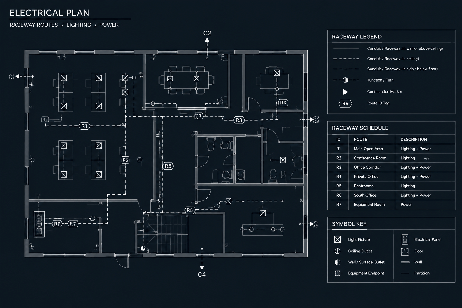
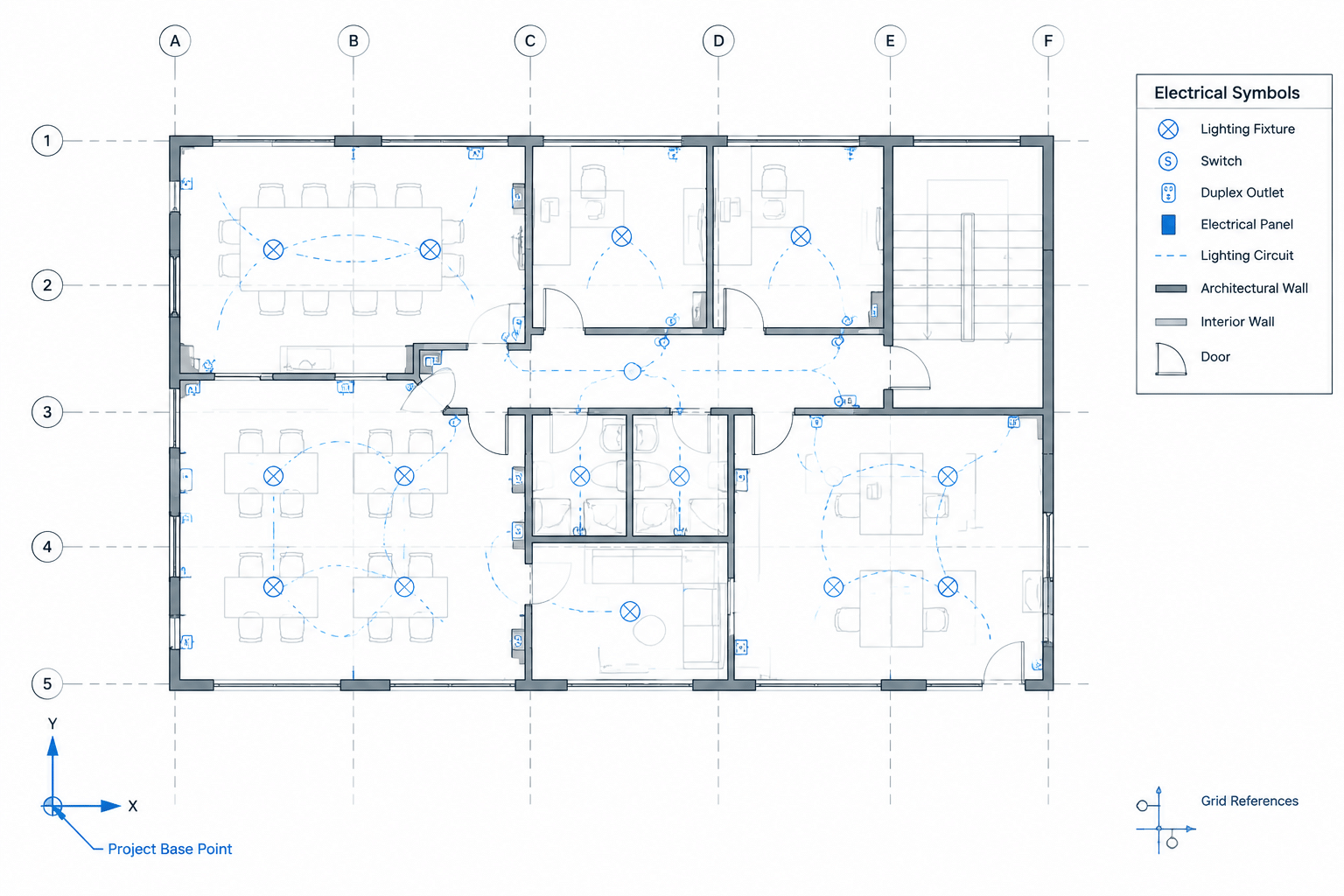
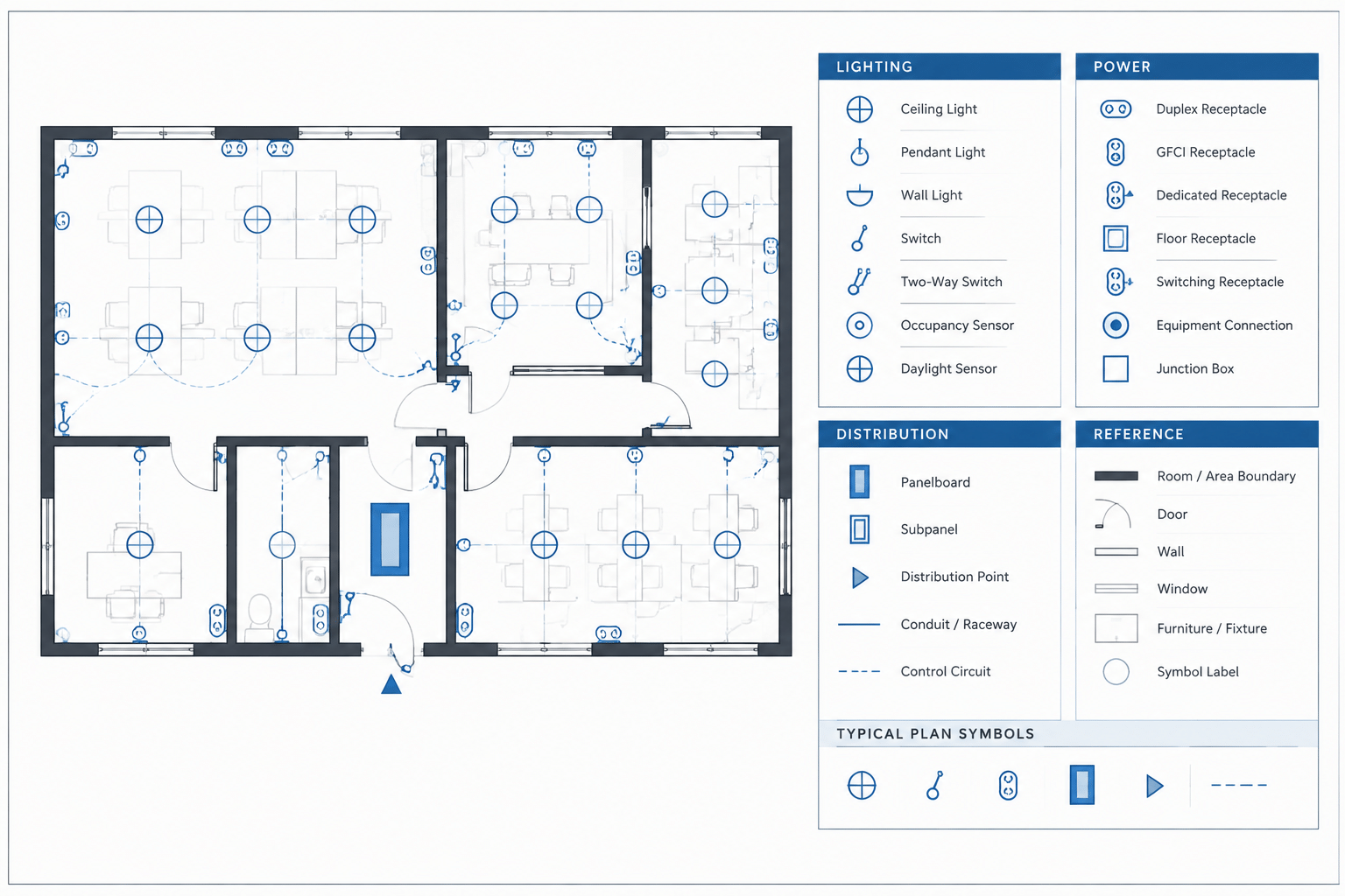
On a floor plan, locate a box where it communicates coordination intent. That may be at a corridor route change, above an accessible ceiling area, near an equipment group, along a vertical pathway, or at a transition between routing conditions. The plan location should be coordinated with structural elements, ceilings, access constraints, equipment, and other building systems.
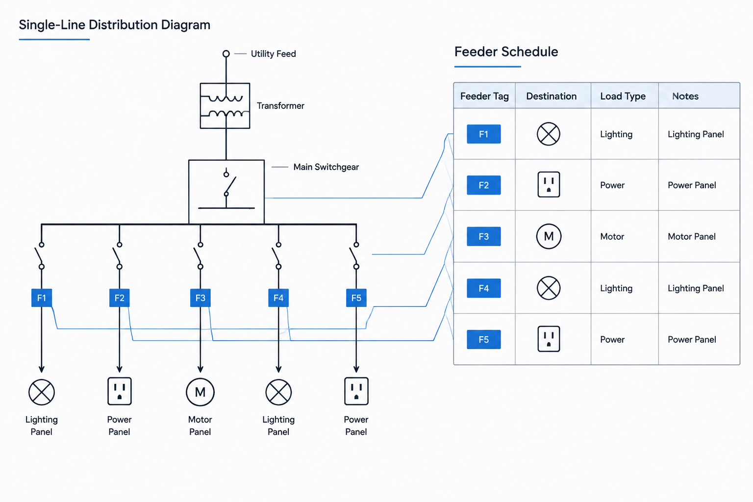
A schematic or single-line diagram uses enclosure symbols differently. It shows electrical relationships rather than a scaled physical position. For example, a diagram may show a junction point between a source and several downstream loads, while the plan shows the actual enclosure location and route geometry. Use matching identifiers so the reader can move between these views without guessing.
When exact physical placement cannot be resolved on the plan, document the limitation explicitly. A note such as a required coordination condition is more useful than presenting an arbitrary location as final. Avoid placing boxes merely to make circuiting lines look tidy if the resulting location conflicts with the building layout.
Coordinate raceways and connection intent
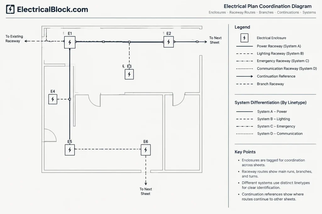
Raceway linework should meet the enclosure symbol consistently. Connections that stop short, pass through the symbol without explanation, or terminate at nearby text can create ambiguity. Establish a drafting rule for the connection point on each block and apply it throughout the drawing set.
The plan should make it possible to understand which routes enter and leave the enclosure. This does not mean every conductor must be graphically represented. Depending on the project, route information may be carried by raceway tags, circuit identifiers, feeder tags, system labels, or references to a conduit schedule.
Branching and pass-through conditions
A branch from an enclosure should be visually different from unrelated crossing linework. Use clear endpoints, junction conventions, and route labels. If a raceway passes through an enclosure without a splice or branch, avoid implying a connection arrangement that has not been designed.
Vertical transitions
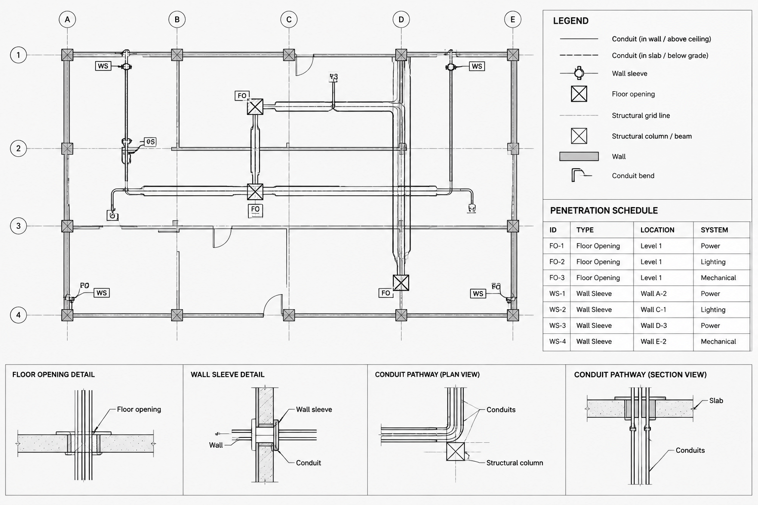
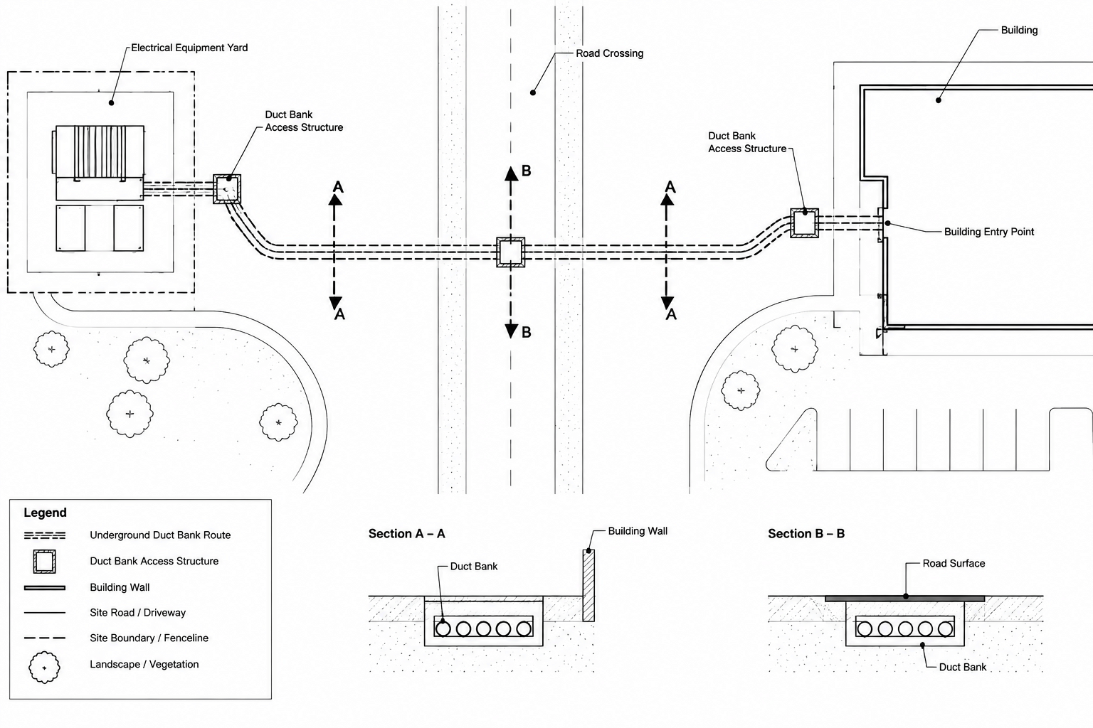
Boxes associated with risers, shafts, roof transitions, or below-grade routes often require references beyond the floor plan. Coordinate their IDs with riser diagrams, enlarged plans, sections, and continuation symbols. A vertical route that appears to end at a box on one floor should have a traceable destination on the next relevant view.
Multiple systems in one area
Power, controls, communications, and signaling boxes may be concentrated in the same ceiling or equipment zone. Separate them by system designation, layer, symbol variant, or tag prefix. Do not rely on CAD color alone because plotted sheets, exports, and field copies may be monochrome.
Use a schedule when plan notes become crowded
A box schedule can remove repetitive information from the plan while preserving a clear record. It is particularly useful when enclosures have different functions, access conditions, routing relationships, or detail requirements.
Possible schedule columns include:
- Box identifier
- Description or intended function
- Associated system
- Plan location or area
- Source reference
- Destination reference
- Entering and leaving raceway references
- Mounting or access condition
- Detail, section, or diagram reference
- Remarks and responsibility notes
Include only fields the project team can maintain reliably. A short, coordinated schedule is more valuable than a large table filled with placeholders or assumptions. If enclosure sizing is shown, it must come from verified project design information rather than a generic CAD template.
Decide when a detail or section is needed
A plan symbol is often insufficient where the enclosure must be coordinated in three dimensions. Add an elevation, section, or enlarged detail when the drawing needs to communicate mounting context, nearby equipment, access direction, clustered raceways, structural interfaces, or transitions between exposed and concealed work.
A useful detail may show the enclosure outline, surrounding construction, route directions, identification tag, and references to related views. Keep the detail diagrammatic unless verified dimensions and installation information are available. Notes should define documentation intent without attempting to replace engineering review, product information, or project specifications.
Organize CAD layers and block data
Separate enclosure symbols from raceway linework and general annotation so each category can be controlled independently. Projects with several electrical systems may use additional layer divisions, but excessive fragmentation can make editing and plotting difficult. The layer structure should support common tasks such as isolating boxes, reviewing routes, producing reflected ceiling coordination views, and checking demolition or phasing status.
Attributes can improve consistency, but they also create maintenance obligations. If a box ID changes, update every plan, schedule, detail, and diagram where it appears. Do not place the same identifier in several unrelated text objects when a managed attribute or data workflow can reduce duplication.
A practical drafting workflow
-
Define the enclosure categories. Decide which items are junction boxes, pull boxes, combined-function enclosures, or special-system boxes.
-
Establish symbols and identifiers. Select readable blocks, tag conventions, connection points, and status graphics.
-
Place boxes from routing and coordination needs. Use the architectural and engineering backgrounds rather than distributing symbols only for graphic convenience.
-
Connect raceway linework. Check that routes enter the intended block connection points and that branches are unambiguous.
-
Add schedule and view references. Move repeated data into a schedule and reference details where physical context matters.
-
Reconcile related drawings. Compare plans with risers, single-lines, conduit schedules, equipment layouts, and system diagrams.
-
Run a final identifier audit. Find duplicate IDs, untagged boxes, unused schedule rows, broken continuation references, and boxes with no clear route association.
Quality-control questions before issue
- Can every scheduled enclosure be found on a drawing?
- Does every tagged box have a clear function or supporting reference?
- Are connected raceways visually attached to the correct symbol?
- Are system types distinguishable without depending only on color?
- Do plan, riser, diagram, and detail identifiers agree?
- Are access and mounting conditions documented where they affect coordination?
- Have generic block notes and unverified placeholder values been removed?
- Are existing and new enclosures clearly differentiated?
- Do continuation references lead to valid destinations?
Well-coordinated junction and pull box drawings create continuity between routing intent and physical layout. By treating each enclosure as a traceable drawing object rather than an isolated symbol, the CAD set becomes easier to review, schedule, revise, and coordinate across disciplines.
Use the enclosure identifier as the coordination key
A junction or pull box identifier should connect the plan symbol to every related schedule entry, diagram, section, and detail. Treating that identifier as a shared coordination key makes it easier to follow a route, review a revision, and detect conflicting information.
Separate stable data from view-specific graphics
Information such as the enclosure identifier, system association, and documented function may need to remain consistent across several views. Location graphics, route geometry, continuation marks, and callouts are specific to the view in which they appear. Keeping these categories distinct helps prevent a local drafting change from creating an unnoticed conflict elsewhere in the set.
Review changes as connected relationships
Moving or retagging a box is not only a symbol edit. The change may affect entering and leaving routes, continuation references, schedule records, diagrams, details, and status graphics. A revision review should follow those relationships rather than checking only the sheet where the edit began.
Clarify which drawing carries each type of information
- Plan: communicates location, nearby coordination context, route direction, and the enclosure tag.
- Schedule: consolidates repeatable descriptions, system associations, references, and project-defined remarks.
- Diagram: explains functional relationships without implying a scaled physical arrangement.
- Detail or section: shows mounting context, access considerations, route grouping, and surrounding construction.
- Legend or criteria note: defines symbol conventions, status graphics, abbreviations, and documentation rules.
Assigning information deliberately reduces duplicate notes and makes discrepancies easier to find. Where a condition remains unresolved, identify it as a coordination item instead of filling the drawing with assumed enclosure data.
Prepare the CAD information for handoff
Before issuing or transferring the files, confirm that enclosure blocks remain editable, attributes contain current values, route endpoints align with the intended connection points, and plotted output remains understandable without CAD color. Remove abandoned tags and placeholder records, then compare the visible sheets with any schedule or data extraction workflow used by the project team.
Frequently asked questions
Can junction boxes and pull boxes use the same CAD symbol?
They can share a basic enclosure graphic if the project’s tags, legend, schedule, or notes clearly distinguish their intended functions. If that distinction affects drawing interpretation, relying on an identical unqualified symbol is not sufficient.
What information should stay on the plan?
Keep information needed to read the location and route relationship directly on the plan, including the identifier and necessary references. Repetitive descriptions and project-defined enclosure data are often easier to manage in a coordinated schedule.
How should an unknown enclosure size be documented?
Do not insert an assumed size into the block or schedule. Use the project’s established method for identifying unresolved information and add verified data only after it has been confirmed through the design process.
Why can raceways appear connected in CAD but look disconnected on a plot?
Line endpoints may not meet the block’s intended connection point, or annotation and masking may obscure the junction. Review the geometry at editing scale and inspect the plotted or exported output used for document delivery.
Is CAD color enough to distinguish different systems?
No. Color can support editing and coordination, but system identity should also be communicated through layers, line conventions, tags, symbols, or labels that remain understandable in monochrome output.
How should a box be coordinated between a plan and a riser diagram?
Use the same enclosure identifier and consistent source, destination, and system references. After revisions, compare both views and verify that continuation marks and related schedule entries still lead to the intended enclosure.

Leave a Reply
You must be logged in to post a comment.