
Integrated circuits symbols are a practical part of electronic schematic drafting. A well-organized CAD block collection can help engineers, designers, and students place recognizable circuit symbols into drawings without recreating each graphic manually.
This reference accompanies the downloadable DWG content and explains how integrated circuit symbols fit into schematic diagrams, PCB-related documentation, electrical layouts, and broader CAD coordination workflows.
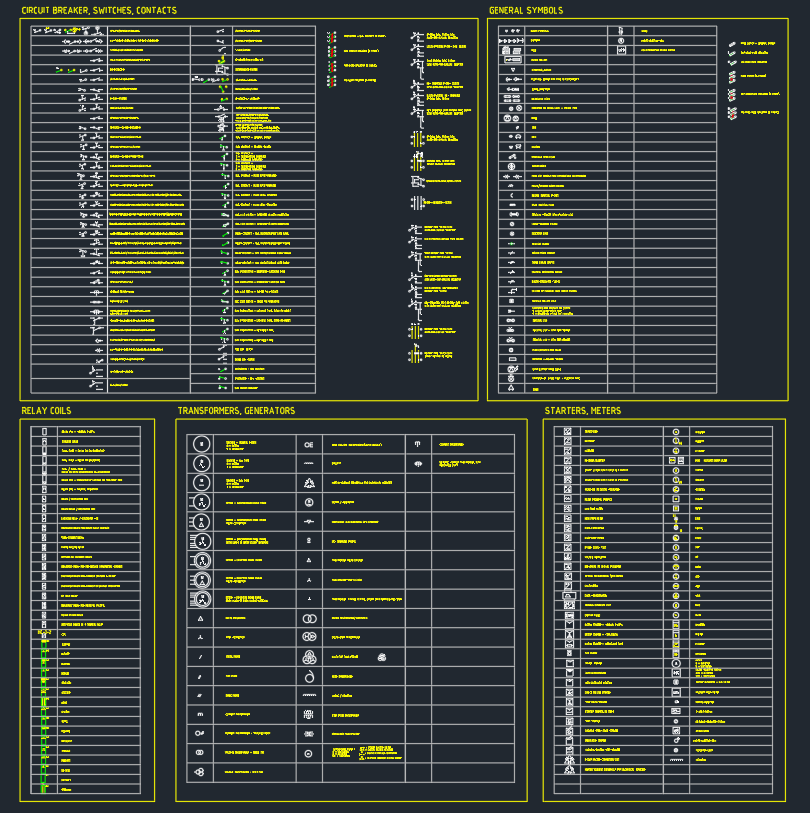
Discover a comprehensive DWG file featuring Integrated Circuits Symbols, perfect for engineers, designers, and students working on electronic schematic diagrams. This CAD Block collection includes a variety of standard integrated circuit symbols, enabling precise and efficient circuit design. The file is fully compatible with AutoCAD and other popular CAD software, ensuring seamless integration into your projects. Ideal for PCB design, electrical layouts, and technical documentation, these integrated circuit symbols streamline your workflow and enhance the accuracy of your electronic schematics. Download now to boost your productivity and maintain industry standards.
Please log in or register to download this file.
How integrated circuit symbols support schematic drafting
An integrated circuit symbol is a graphical representation of a device or functional component in a schematic. It helps readers understand the intended circuit relationship without relying on a physical view of the component. The symbol should be placed, oriented, and labeled consistently with the drawing’s notation and documentation practices.

Symbol blocks and drawing consistency
Using reusable CAD blocks improves consistency across related sheets and projects. Before inserting a block, check the drawing’s symbol style, text placement, layer organization, insertion behavior, and connection points. These details matter when a schematic is edited, reviewed, printed, or shared with another CAD user.
Schematic symbols versus physical component graphics
A schematic symbol communicates electrical function and connectivity; it does not necessarily describe the physical outline or package of the component. Keep logical schematic documentation separate from board layout footprints, enclosure outlines, and equipment views unless the project specifically combines those representations.

Practical review checklist
- Confirm that the selected symbol represents the intended integrated circuit function.
- Check connection points and nearby wires after insertion.
- Keep reference designators, labels, and notes readable at the drawing scale.
- Use the same symbol conventions throughout related schematic sheets.
- Review the finished drawing for overlaps, ambiguous connections, and inconsistent orientation.
Related CAD documentation topics
This DWG resource fits naturally with electrical legends, schematic symbols, panel documentation, equipment layouts, and other drawing-reference materials. Connecting these topics in a project workflow can make it easier to maintain consistent drafting conventions across electrical and electronic documentation.
Frequently asked questions
What is included in an integrated circuits symbols DWG file?
The source content describes a CAD block collection containing integrated circuit symbols for use in electronic schematic diagrams and related technical documentation. Review the downloaded file in your CAD environment to confirm the available block names and graphic conventions.
Can these symbols be used in AutoCAD?
The source content identifies the file as compatible with AutoCAD and other popular CAD software. Compatibility can still depend on the software version, drawing settings, and how blocks, layers, and annotation styles are handled in the target project.

Are schematic symbols the same as PCB footprints?
No. A schematic symbol represents logical function and electrical connections, while a PCB footprint represents a physical board-mounting arrangement. They may be related in a design workflow, but they serve different documentation purposes.
What should be checked before using a symbol in a project?
Check the symbol’s identity, connection points, labels, orientation, layer behavior, and consistency with the project’s drafting conventions. A qualified design professional should verify the completed documentation for the intended application.
Leave a Reply
You must be logged in to post a comment.