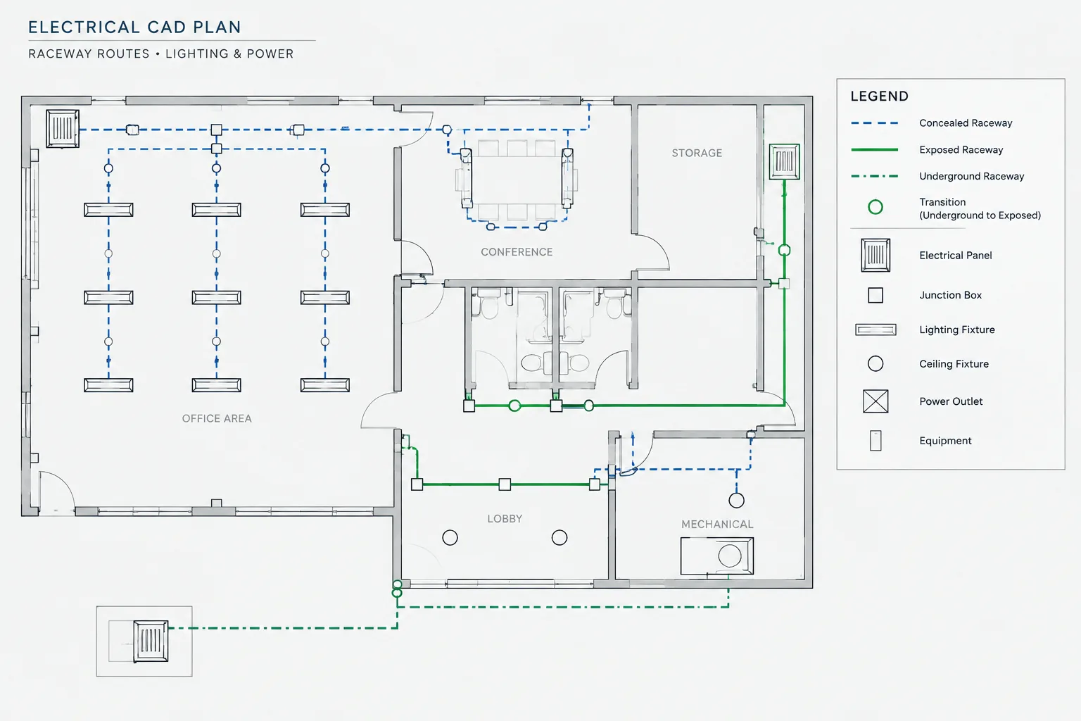
Raceway linework must communicate more than horizontal direction. A clear electrical CAD plan also indicates the intended installation condition, drawing status, route identity, and points where the pathway changes from concealed to exposed or underground.
The most reliable approach combines visible plotting conventions with coordinated layers, annotations, legends, schedules, and detail references. This keeps the issued drawing understandable even when readers cannot inspect CAD object properties.
A raceway line on an electrical plan can represent very different installation conditions. It may be concealed above a ceiling, exposed within an open structure, routed below a slab, or buried outside the building. If those conditions are not communicated clearly, a visually neat drawing may still leave important questions unanswered.
There is no single graphic convention that fits every office, client, or project. Raceway line types in electrical CAD should therefore be treated as part of a coordinated documentation system rather than as isolated drafting choices. The linework, layer names, tags, notes, sections, schedules, and legend all need to convey the same intent.
This guide explains how to build that system without turning a power plan into a maze of competing lines.
Why Raceway Installation Conditions Matter on Drawings
A plan view primarily shows horizontal position. It does not automatically explain whether a route is overhead, exposed on a wall, within a concealed ceiling space, below a floor, or underground. Two routes can follow the same plan alignment while occupying entirely different vertical zones.
Making the installation condition visible helps drawing users:
- Interpret where a route is intended to pass through the building.
- Coordinate raceways with ceilings, structure, mechanical services, and architectural finishes.
- Identify transitions between concealed, exposed, below-grade, and equipment-area conditions.
- Connect plan routes with sections, details, risers, and schedules.
- Recognize where the designer has established an approximate path rather than a precisely coordinated alignment.
The goal is not to illustrate every bend. The goal is to communicate routing intent at the level appropriate for the drawing.
Choose a Graphic Vocabulary Before Drafting
Before assigning line types, decide which raceway conditions the project actually needs to distinguish. Too many categories can be as difficult to read as too few.
A typical documentation vocabulary might separate the following concepts:
- Concealed raceway in an accessible ceiling or building cavity.
- Exposed raceway visible within the occupied or service space.
- Raceway below a floor or slab.
- Underground or site raceway.
- Existing raceway to remain.
- Raceway to be removed, abandoned, or modified.
- Future or spare pathway.
These categories should not be adopted automatically. They should reflect the project scope and the distinctions that matter to coordination and construction documentation.
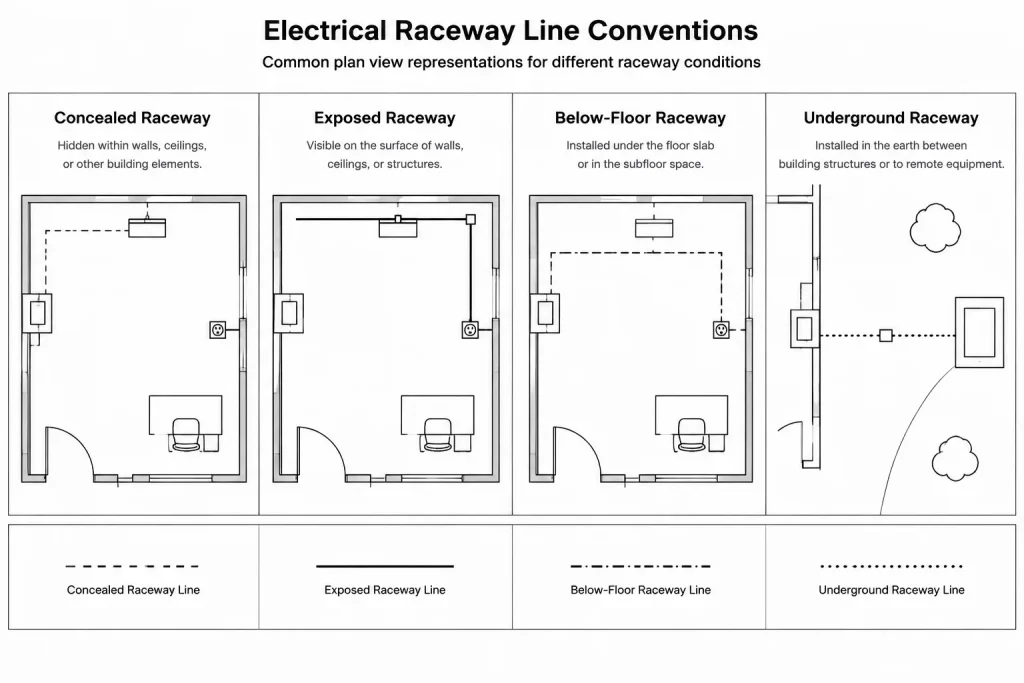
Do Not Rely on Color Alone
Color can help CAD users work efficiently, but it may disappear in monochrome plots, grayscale PDFs, photocopies, or exported backgrounds. A condition should remain understandable through a combination of line type, lineweight, tag, note, or layer-controlled graphic treatment.
Avoid Treating Dashed Lines as Self-Explanatory
A dashed line could mean concealed, below grade, existing, demolition, overhead, or simply secondary information. Without a legend or contextual label, the reader must guess. If a dashed convention is used, define it clearly and confirm that it does not conflict with other disciplines or project status graphics.
Comparing Common Raceway Graphic Methods
| Method | Best use | Potential limitation |
|---|---|---|
| Distinct line types | Separating a small number of routing conditions on one plan | Patterns may become unclear at different viewport scales |
| Dedicated CAD layers | Controlling visibility, plotting, and plan-specific displays | Layer identity may not be visible in printed output |
| Route tags | Identifying systems, destinations, or installation conditions | Too many tags can crowd the plan |
| Keynotes or leaders | Calling out unusual transitions or local conditions | Repeated notes can create clutter |
| Sections and details | Explaining elevation, penetrations, and stacked routes | Requires accurate plan references and coordination |
| Separate plan views | Showing dense overhead, below-floor, or underground systems independently | Routes must remain coordinated across multiple views |
Most effective drawing sets combine several of these methods. Layers manage the CAD file, line types provide immediate visual distinction, tags identify routes, and sections explain conditions that cannot be resolved in plan.
Build a Layer Structure Around Meaning
Raceway layers should help the drafting team isolate meaningful content. A layer structure might distinguish system, installation condition, drawing status, or some combination of those properties. The exact naming format should follow the project’s CAD requirements.
For example, a team may decide that system identity is handled by the base layer name while exposed, concealed, and underground conditions are represented by consistent suffixes. Another team may keep raceway geometry on a common system layer and use separate display layers for annotations and route identifiers.
Whatever method is chosen, avoid creating layers that only one drafter understands. Document the structure in the project CAD guide or layer key, and test common visibility combinations before the drawing set grows.
Separate Geometry from Annotation When Useful
Route lines and their tags do not always need to share a layer. Separating them can allow the drafter to simplify an overall plan, show more annotation in an enlarged plan, or temporarily hide tags during coordination review. However, route identifiers should not be hidden in the issued view when they are necessary to interpret the linework.
Use Layer States for Review, Not as the Only Explanation
Layer states can create useful coordination views, such as exposed raceways only or underground routes only. These views are valuable inside CAD, but the issued sheet must still be understandable without access to the working layer controls.
Draft Concealed and Exposed Routes Deliberately
Concealed routes are often shown diagrammatically because their exact path may depend on accessible spaces and trade coordination. Exposed raceways typically need more deliberate plan placement because their alignment can affect visible surfaces, equipment access, and coordination with structure.
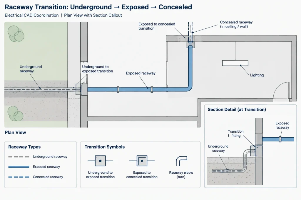
When exposed routing is important, consider showing:
- The intended wall, ceiling, or structural zone.
- Changes in direction that affect visible alignment.
- Connection points at equipment or devices.
- Transitions into concealed spaces.
- References to elevations or details where vertical placement matters.
Do not imply precision that the drawing does not actually establish. If a line is schematic, a note or route designation should make that level of intent clear. If the route has been coordinated to a specific corridor or equipment zone, the drawing should provide enough context to preserve that decision.
Document Below-Floor and Underground Raceway
Below-floor and underground routes often require more than a different line type. Their coordination may depend on foundations, trenches, floor penetrations, equipment pads, site utilities, or transitions at building entrances.
Useful documentation can include:
- Start and end points tied to identifiable equipment or pull points.
- Route tags linked to a schedule or diagram.
- Callouts at entries, stub-ups, sleeves, and direction changes.
- Sections where depth relationships or utility crossings must be understood.
- Match lines and continuation references when a route crosses sheets.
- Clear differentiation between new, existing, future, and removed pathways.
A single dashed path across a site plan is rarely enough if the route interacts with other underground systems. Use the plan to establish alignment and use profiles, sections, or details to explain vertical relationships where needed.
Show Transitions as Documented Events
The point where a raceway changes condition is often more important than the uninterrupted route. Examples include an underground route rising into equipment, an exposed route entering a wall, or a concealed pathway emerging in an open-ceiling area.
At each significant transition, provide an understandable combination of graphic change and annotation. Possible methods include:
- Changing the line type at the transition point.
- Adding a short leader note.
- Placing a transition symbol defined in the legend.
- Referencing a section, elevation, or installation detail.
- Using a route tag that continues across both conditions.
Avoid changing line type at an arbitrary point with no explanation. Readers should be able to identify why the graphic condition changes.
Coordinate Plans, Diagrams, and Schedules
A raceway route may appear on a floor plan, site plan, riser diagram, one-line diagram, cable schedule, or conduit schedule. These representations serve different purposes, but their identifiers and endpoints should agree.

Use stable route or feeder references where cross-document coordination is necessary. If a path is tagged on the plan, verify that the same tag points to compatible origin, destination, status, and system information elsewhere in the set. A route shown as existing on one view should not appear as new on another without a documented scope reason.
Diagrams generally describe connectivity rather than physical alignment. Plans describe location more directly. Do not force a diagram to duplicate every plan bend, and do not assume that a plan route alone fully explains electrical connectivity.
Create a Focused Raceway Legend
The legend should define only the graphic conventions used in the issued drawings. Include representative samples of line types, route symbols, transition markers, and status graphics where they are necessary for interpretation.
A useful legend entry explains meaning rather than merely repeating a layer name. For example, it should distinguish whether a graphic represents a concealed pathway, an approximate underground route, or an exposed route requiring visible alignment coordination.
Plot-test the legend at the same output conditions as the plans. A line pattern that looks distinct in model space may become nearly continuous or disappear when printed through a viewport.
Raceway Drawing Review Checklist
- Can each line type be understood from the legend?
- Do the graphics remain distinct in the intended plot output?
- Are exposed, concealed, below-floor, and underground conditions separated where relevant?
- Are significant transitions labeled or referenced?
- Do route tags agree with schedules, diagrams, and destination equipment?
- Are continuation points coordinated across sheets?
- Are existing, new, demolition, and future conditions visually unambiguous?
- Have dense areas been supported with enlarged plans or sections?
- Are xref graphics prevented from masking or imitating electrical routes?
- Does the drawing avoid implying an exact route where only schematic intent has been established?
Use CAD Graphics to Support Design Intent
Raceway drafting is most effective when each graphic distinction answers a real coordination question. Layers should organize the file, line types should aid recognition, tags should connect related information, and sections should clarify vertical conditions.
Before issuing the drawings, review the route system as a reader would: without relying on object properties, internal layer knowledge, or informal office habits. If concealed, exposed, and underground pathways can be interpreted from the plotted sheet and coordinated references, the CAD documentation is doing its job.
All route conventions, installation descriptions, and project-specific conditions should be verified against the applicable design criteria, project requirements, and coordinated discipline information before use in a real drawing set.
A Practical Hierarchy for Raceway Graphics
When developing raceway line types in electrical CAD, begin with the information that must remain visible on the plotted sheet. Use the strongest graphic distinction for conditions that affect interpretation, coordination, or scope. Use layers and object properties to support that distinction rather than replace it.
A practical documentation hierarchy is:
- Plan linework: Establishes the approximate or coordinated horizontal route.
- Graphic treatment: Differentiates concealed, exposed, below-floor, underground, and drawing-status conditions.
- Route annotation: Connects the path to its origin, destination, system, schedule, or related diagram.
- Transition callout: Identifies where the installation condition changes.
- Section or detail reference: Explains vertical relationships that cannot be understood in plan.
- Legend definition: Confirms how each line pattern, symbol, and status treatment should be read.
This hierarchy also provides a useful quality-control sequence. Review the route first as plotted linework, then confirm its tags, transitions, references, and corresponding information elsewhere in the drawing set.
Check the Drawing Outside the Authoring File
A convention can appear clear to the drafter while remaining ambiguous to everyone else. Review the issued-format output without selecting objects or checking layer names. Confirm that line patterns remain recognizable, route labels do not mask connections, and background graphics cannot be mistaken for electrical pathways.
Where multiple conditions overlap, adding more line styles may not solve the problem. A separate plan, enlarged view, section, or focused detail can communicate the relationship more clearly than increasingly complex plan graphics.
Frequently Asked Questions
Does a dashed raceway line always mean concealed?
No. Dashed linework can represent several conditions depending on the drawing system. Its meaning should be defined in the project legend and reinforced by tags or notes when confusion is possible.
How should underground raceway differ from concealed raceway?
Use a documented combination of line type, layer assignment, route tag, or annotation that remains distinct in the final plot. Underground routes may also need sections or details where entrances, crossings, and vertical transitions matter.
Should exposed raceway be drawn more precisely?
Exposed routing often needs closer coordination because its visible alignment can interact with structure, equipment, and finishes. The drawing should still avoid implying exact placement unless that placement has actually been established.
Can CAD layers alone identify raceway conditions?
Layers are useful for editing, filtering, and display control, but their names are not normally visible on an issued sheet. Important conditions should also be communicated through plotted graphics and annotations.
What should happen when raceway conditions overlap in plan?
Consider route tags, offset linework, enlarged plans, separate views, or sections. The selected method should clarify the relationship without suggesting a physical separation that has not been coordinated.
How should a change from underground to exposed raceway be shown?
Treat the change as a documented transition. A graphic change can be paired with a note, transition marker, route identifier, or reference to a section or detail.
Should plan routes match one-line or riser diagrams exactly?
The identifiers, endpoints, system intent, and status should agree. The graphics do not need to match geometrically because diagrams communicate connectivity while plans communicate location.


Leave a Reply
You must be logged in to post a comment.