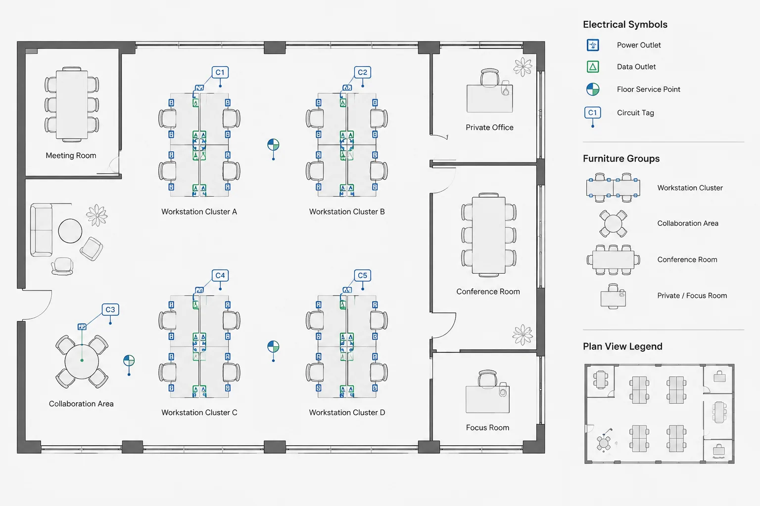
Modular workstations, conference tables, movable partitions, and systems furniture can create a difficult documentation boundary. Architectural plans may show the furniture arrangement, electrical plans may show building connections, and furniture-vendor drawings may show internal distribution. If those documents use different identifiers or connection locations, the drawing set can appear coordinated while still leaving important questions unanswered.
A clear modular furniture power and data plan does not attempt to reproduce every component inside a proprietary furniture system. Its purpose is to show where building services meet the furniture, identify the intended connection type, communicate pathway requirements, and direct readers to the documents that define the remaining work. The following workflow focuses on those CAD and documentation tasks.
Begin with a reliable furniture background
Obtain the current furniture plan from the architect, interior designer, owner, or furniture vendor. Whenever possible, reference it into the electrical file rather than tracing workstation outlines. A referenced background is easier to replace when layouts change and reduces the risk of retaining obsolete desk positions.
Before circuiting or placing connection symbols, review the background for:
- Workstation group limits and individual station identifiers
- Conference tables, reception desks, training tables, and other powered furniture
- Panels or partitions that may contain internal power or communications pathways
- Floor boxes, poke-through devices, wall feeds, or ceiling-fed service poles shown by others
- Access aisles, doors, glazing, columns, and other constraints near proposed feeds
- Furniture revision dates or issue identifiers
Keep furniture graphics visually subordinate to the electrical scope. A screened or lighter background generally makes connection symbols, circuit annotations, and pathway notes easier to read. If the source plan contains dense finishes, dimensions, or product labels, use layer controls to display only the information needed for coordination.
Define the drawing responsibility boundary
One of the most important decisions is where the electrical contract documentation stops and the furniture-vendor documentation begins. The boundary may vary by project and should not be assumed from a generic CAD block.
The electrical plan commonly documents building-side items such as branch-circuit origin, raceway routing intent, junction points, floor boxes, wall outlets, or other connection provisions. Furniture documents may define internal harnesses, modular connectors, receptacle placement within panels, data faceplates, and manufacturer-specific parts. Procurement and installation responsibility can differ even when the physical connection is shown in the same location.
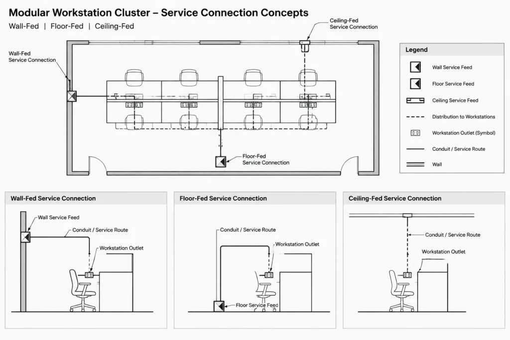
Use notes and references to make this division visible. Avoid vague labels such as “power furniture” when the reader needs to know whether the symbol represents a floor outlet, a junction point, a flexible connection provision, or a vendor-supplied furniture inlet. Exact connection methods and ratings must be verified against the selected furniture system and project requirements.
Choose symbols by function, not appearance
A workstation plan can become confusing when a single generic outlet symbol is used for every interface. Symbols should distinguish the function of each building connection while remaining consistent with the project legend.
| Plan item | What the graphic should communicate | Typical coordination reference |
|---|---|---|
| Wall connection | Service provided from a wall to adjacent furniture | Architectural elevation or electrical detail |
| Floor connection | Service delivered through or at the floor near a furniture group | Floor box schedule, slab plan, or device detail |
| Ceiling-fed connection | Service routed from above to freestanding furniture | Ceiling plan, section, or service-pole detail |
| Power interface | Building power termination or connection point | Panel schedule and circuit annotation |
| Communications interface | Data, voice, or other low-voltage pathway endpoint | Telecommunications plan and outlet schedule |
| Combined service location | Multiple systems coordinated at one furniture feed | Enlarged plan or coordination detail |
Do not imply that power and communications share the same compartment or pathway merely because their symbols are placed together. The drawings should show conceptual proximity without concealing required separation or product-specific restrictions. When the floor plan is too crowded, use a combined tag linked to an enlarged detail or schedule.
Place connections from verified control points
Furniture feeds should be located from stable architectural control points rather than from the visual center of a workstation cluster. Grid lines, column lines, wall faces, or other coordinated references are more dependable than movable desks and chairs.
For floor-based connections, request a dimensioned vendor connection plan or approved coordination layout. A furniture outline alone may not reveal which panel accepts the feed, the usable entry zone, or conflicts with internal supports. Show the intended interface point on the electrical plan and provide dimensions on an appropriate installation or coordination drawing when the project workflow requires them.
If final furniture information is unavailable, identify provisional locations clearly. Do not present unverified coordinates as final. A hold note, coordination cloud, or tracked issue item is more useful than false precision.
Coordinate power circuit documentation
Each furniture power connection should be traceable to its electrical source using the project’s established circuiting method. This may involve a panel-and-circuit annotation, a homerun reference, a keyed circuit tag, or a schedule entry. The plan, panel schedule, and supporting diagrams should use matching identifiers.
Modular furniture may contain several internal receptacles even though the building plan shows only a limited number of interface points. Avoid treating a building connection symbol as a complete count of furniture receptacles. Instead, state whether detailed device quantities are defined by the furniture package, electrical drawings, or another schedule.
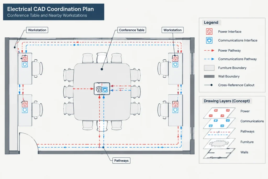
Where furniture arrangements include different operational groups, the documentation may also need to distinguish circuits serving separate furniture sections or designated equipment. Such grouping should come from the project design criteria and verified vendor information, not from assumptions based on workstation geometry.
Show data and communications intent separately
Power and data frequently arrive at the same workstation group, but their documentation should remain independently traceable. Use distinct layers, symbols, tags, or plan views so that communications outlets and pathways can be reviewed without relying on power circuit graphics.
At minimum, the drawings should clarify:
- The building-side communications outlet or pathway endpoint
- Whether cabling continues through furniture by others
- The furniture group or table served
- The related outlet, cable, or room identifier used in schedules
- Any required reference to a telecommunications detail or vendor diagram
Avoid drawing detailed internal cable routes unless they are actually part of the project documentation. Simplified continuation arrows or interface tags are often clearer than speculative paths through proprietary furniture panels.
Use enlarged plans where interfaces overlap
An enlarged furniture connection plan is useful when a room contains dense workstation clusters, multiple floor devices, or several systems converging at one location. The enlarged view can show connection tags, pathway directions, furniture group labels, and references without overloading the overall floor plan.
Maintain a clear relationship between the overall plan and enlarged view. Use matching room names, furniture identifiers, detail callouts, and connection tags. Avoid duplicating different circuit information in both views unless the CAD workflow provides a reliable way to keep it synchronized.
Organize CAD layers for controlled visibility
Separate the graphics according to system and purpose. A practical structure may include layers for furniture backgrounds, building power interfaces, communications interfaces, circuiting, pathway graphics, tags, notes, and coordination zones. The exact names should follow the project CAD standard.
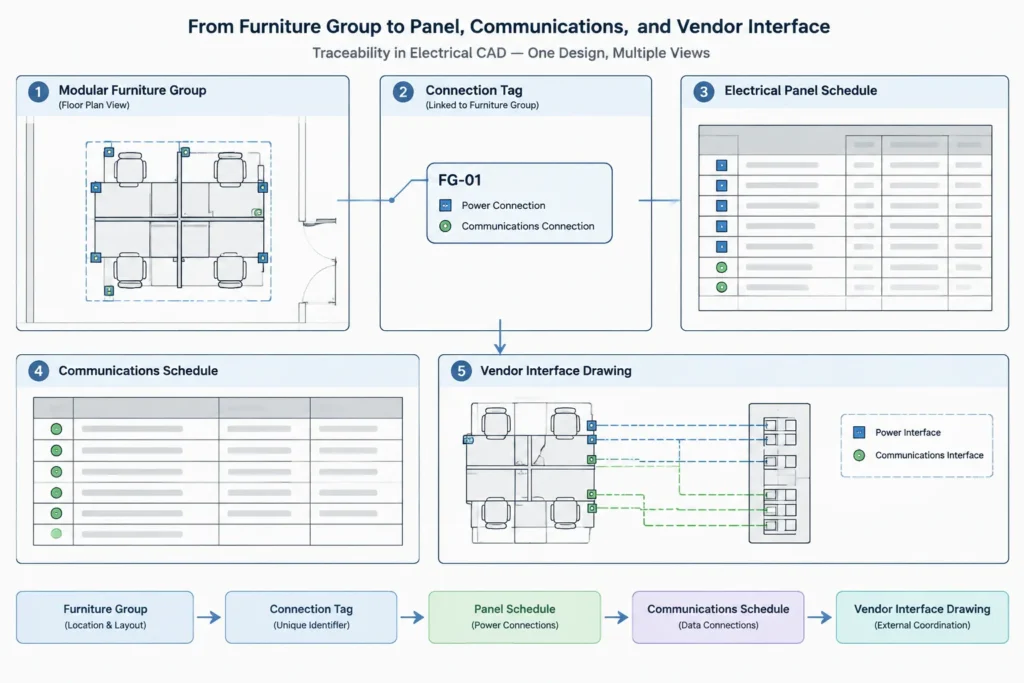
This separation allows the drafter to create focused plots for electrical review, communications coordination, furniture-vendor review, or field layout. It also makes revisions safer because connection symbols can be edited without altering the referenced furniture arrangement.
Track changes to furniture and connection points
Furniture layouts often change after electrical plans have been developed. A moved workstation group can leave a floor connection exposed, place a wall feed too far from its intended panel, or disconnect a plan tag from the correct furniture identifier.
During each background update, compare more than outlines. Review:
- Added, removed, rotated, or renumbered workstation groups
- Changed table sizes and connection zones
- Moved floor boxes or revised wall-feed locations
- Changes in the number or type of service interfaces
- New partitions or millwork that affect pathways
- Tags that no longer match schedules or vendor drawings
Revision clouds alone are not a complete coordination method. Maintain an issue log or checklist that records unresolved furniture information, responsible parties, and drawing references.
Perform a final cross-document review
Before issuing the drawings, follow each connection in both directions. Starting at the furniture group, locate its power and data interface symbols, related tags, source or pathway references, schedule entries, and details. Then begin at the panel schedule or communications schedule and confirm that every listed furniture connection appears on the correct plan.
Also verify that legends define the symbols actually used, notes do not conflict with vendor documents, and provisional locations remain visibly identified. CAD blocks should be treated as graphic tools rather than proof that a connection method is suitable. Final locations, connection types, product compatibility, dimensions, and project requirements must be checked against current design documents and selected equipment.
Good modular furniture documentation makes the interface understandable without redrawing the entire furniture system. By controlling backgrounds, separating systems, using traceable tags, and clearly defining responsibility boundaries, the electrical CAD set becomes a practical coordination tool for designers, vendors, reviewers, and installers.


Leave a Reply
You must be logged in to post a comment.