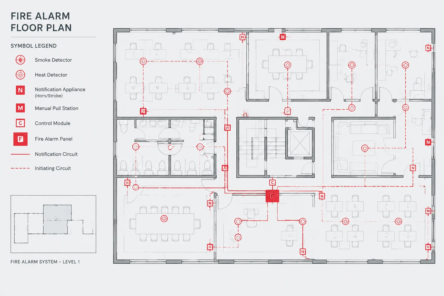
Fire alarm plans communicate more than device locations. A coordinated drawing set must also explain device types, system relationships, circuit intent, monitoring interfaces, control functions, and connections to other disciplines. If these layers of information are placed on one plan without a clear structure, the drawing can quickly become difficult to read.
This guide explains how to develop fire alarm plans in CAD as documentation. It does not determine required system coverage, device placement, wiring methods, or compliance. Those decisions must be established by qualified project professionals using the applicable project criteria, adopted requirements, manufacturer information, and authority review.
Understand the role of each fire alarm drawing
A floor plan, riser, detail, and sequence matrix describe different aspects of the same system. Trying to make one drawing perform every role usually creates clutter or ambiguity.
| Drawing or schedule | Primary purpose | Typical information |
|---|---|---|
| Floor plan | Shows spatial coordination | Device locations, tags, circuit paths, room context, interfaces, and references |
| Riser diagram | Shows system hierarchy | Control equipment, network relationships, circuit groups, floors, and remote equipment |
| Device legend | Defines graphic language | Symbols, abbreviations, mounting distinctions, and device descriptions |
| Device or point schedule | Organizes repeated data | Tags, types, locations, functions, and associated equipment |
| Sequence matrix | Documents cause-and-effect intent | Initiating events, control responses, notifications, releases, and supervisory actions |
| Typical detail | Clarifies recurring conditions | Interfaces, mounting concepts, equipment relationships, and special coordination |
Information should appear where it is easiest to understand and maintain. For example, a plan can reference an interface point while a matrix describes what that interface is intended to do.
Build a project-specific symbol system
Start with a controlled fire alarm symbol library rather than collecting unrelated blocks from older projects. Symbols should share a consistent graphic style, insertion point, plotted size, and attribute structure. A symbol that looks acceptable in model space may still be unreadable at the intended sheet scale, so test blocks in an actual plotted view.
The symbol should identify the device category without attempting to contain every technical property. Detailed data can be carried by a tag, schedule, keynote, or specification reference. Common categories may include:
- Initiating devices and manual stations
- Audible, visible, or combined notification appliances
- Monitor, control, relay, and interface modules
- Control panels, annunciators, and remote power equipment
- Duct, suppression, elevator, smoke-control, or mechanical interfaces
- Special detection devices where required by the project design
Avoid relying on color as the only means of distinguishing devices. Printed sets, reduced sheets, and grayscale review copies may remove that distinction. Shape, abbreviation, tag, or linework should preserve the meaning.
Use block attributes carefully
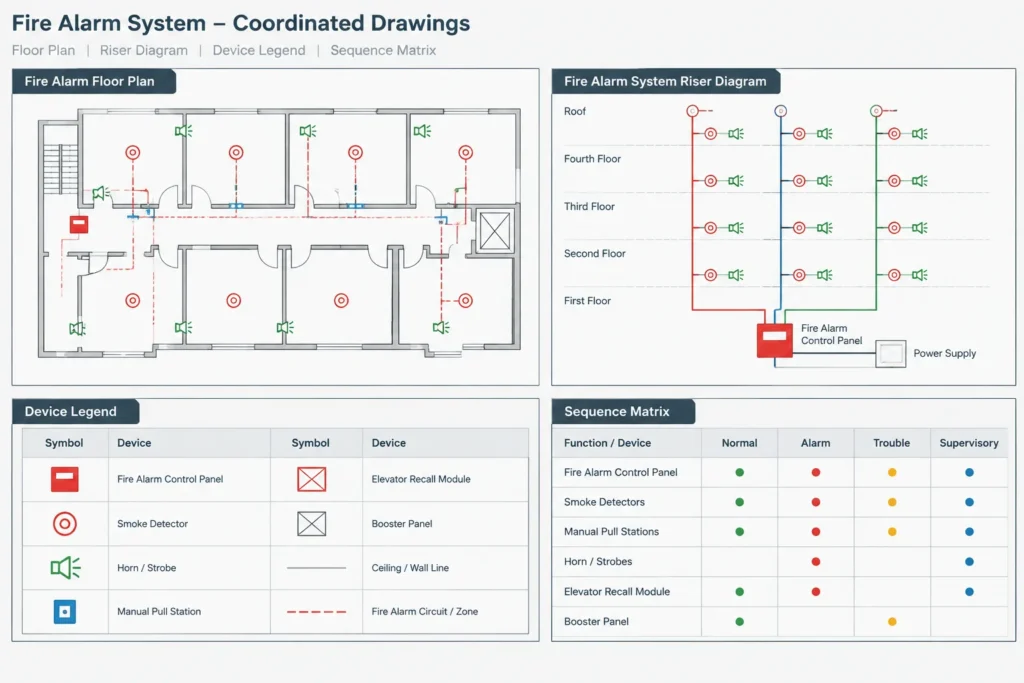
Attributes can hold device identifiers, circuit references, zone designations, mounting notes, or comments. Keep attribute fields limited to information that will be maintained reliably. If the same value is manually entered in a block, schedule, and riser, conflicting data can develop during revisions.
Place attributes so they remain readable when the symbol rotates. Where a device appears close to a wall, ceiling feature, or another symbol, use a movable tag or leader rather than distorting the base block.
Separate symbols, circuits, and background information by layer
A disciplined layer structure allows the drafter to control hierarchy and create different views from the same coordinated model. The exact naming convention should follow the project CAD standard, but separate functional groups are useful.
- Fire alarm devices and equipment
- Device tags and annotations
- Circuit or pathway graphics
- Interface points and control references
- Coverage or zoning graphics, when used
- Demolition, existing, relocated, and new work
- Match lines, detail references, and viewport notes
Architectural and reflected ceiling backgrounds should remain visually subordinate. Doors, room names, ceiling geometry, mechanical equipment, and vertical transportation elements may all be important, but they should not overpower fire alarm symbols or circuit paths.
Place devices using the correct coordination background
Different devices depend on different background information. Ceiling-mounted devices may need coordination with the reflected ceiling plan, while wall-mounted devices are often documented against architectural plans and elevations. Equipment interfaces may depend on mechanical, electrical, elevator, suppression, or security drawings.
Before placing blocks, confirm that the referenced backgrounds share the project coordinate system and represent the current design issue. Avoid moving an external reference merely to make it align visually. A coordinate or source-file problem should be corrected through the project coordination process.
Keep devices out of door swings, casework, glazing, access panels, and other obvious conflicts. This is a drawing coordination check, not a substitute for field verification or code-based placement review.
Show circuit intent without creating a wiring maze
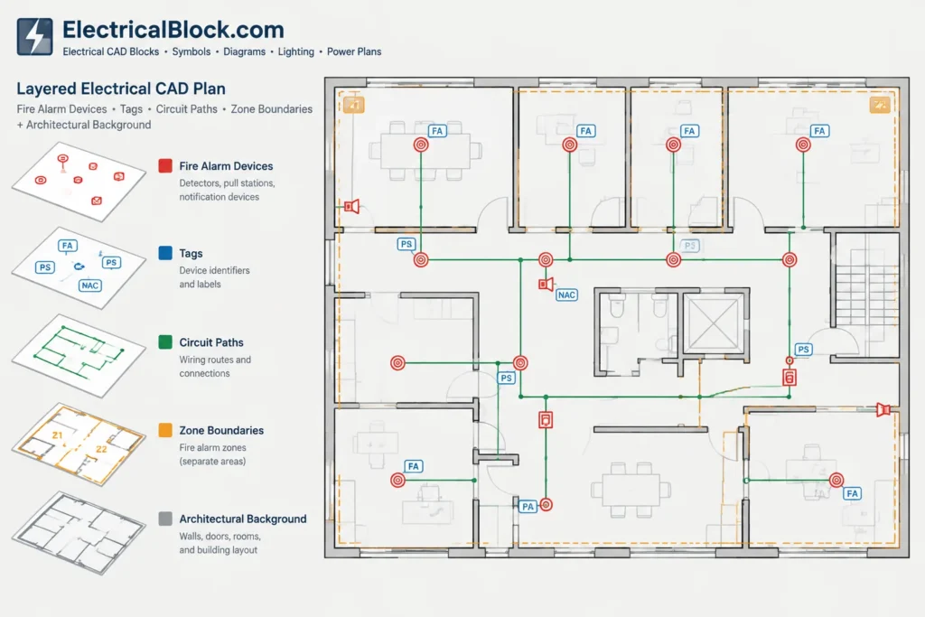
Circuit graphics on a fire alarm plan are often diagrammatic. Their purpose is to group devices and communicate intended relationships, not necessarily to represent exact installed routing. State that distinction in the drawing notes when appropriate.
Use consistent line types or layer assignments for different pathway categories. Circuit identifiers should agree with the riser and any supporting schedules. Where a circuit continues beyond the visible plan area, provide a clear continuation reference instead of allowing the line to stop without explanation.
Control circuit-line density
Long circuit paths can obscure room names and device symbols. Improve clarity by:
- Routing lines around, rather than through, symbols and important annotations
- Using branch graphics consistently
- Applying continuation tags at match lines or enlarged plan boundaries
- Moving detailed equipment connections to an enlarged plan or diagram
- Avoiding decorative line jogs that imply precision the drawing does not provide
Terms such as signaling line circuit, initiating device circuit, and notification appliance circuit describe specific system relationships. Use terminology that matches the actual design basis rather than applying a generic circuit label to every connected device.
Coordinate zones, addresses, and device tags
A zone, circuit, device address, and room number are not interchangeable. Each identifies a different aspect of the documentation. The drawing should make clear which value a tag represents.
For example, a device may have a unique drawing identifier while also belonging to a circuit or reporting group. If all of this information is packed into one symbol, the plan may become difficult to maintain. A concise device tag linked to a schedule is often clearer.
When zone boundaries or reporting areas are shown graphically, place them on a separate layer and give them a restrained plot style. Boundary graphics should not hide device symbols or suggest a rated construction boundary unless that is explicitly what they represent.
Document interfaces with other systems
Fire alarm drawings commonly reference equipment designed by other disciplines. Examples may include air-handling equipment, smoke-control components, elevators, access-controlled doors, suppression systems, generators, or other monitored equipment. The fire alarm plan should identify the interface and its intended relationship without silently assuming responsibility for every connected component.
Use a stable equipment identifier that matches the corresponding discipline’s drawings. If a mechanical unit is renamed, the fire alarm plan, riser, matrix, and point schedule should be reviewed together. Generic notes such as “connect to equipment” are less useful than a coordinated tag and a reference to the relevant control function.
Coordinate the floor plan with the riser and sequence matrix
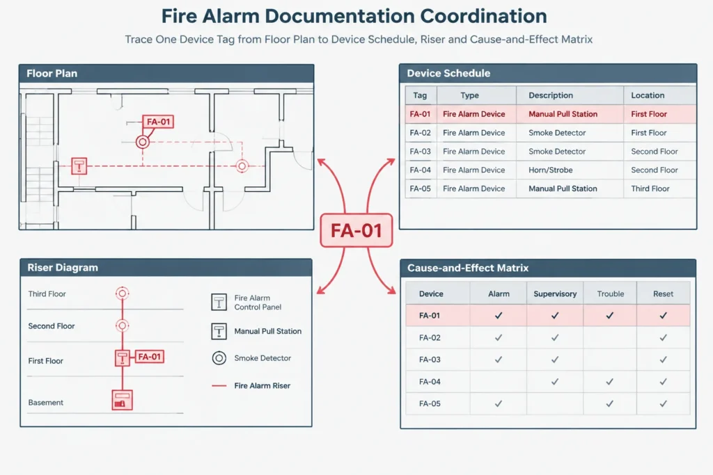
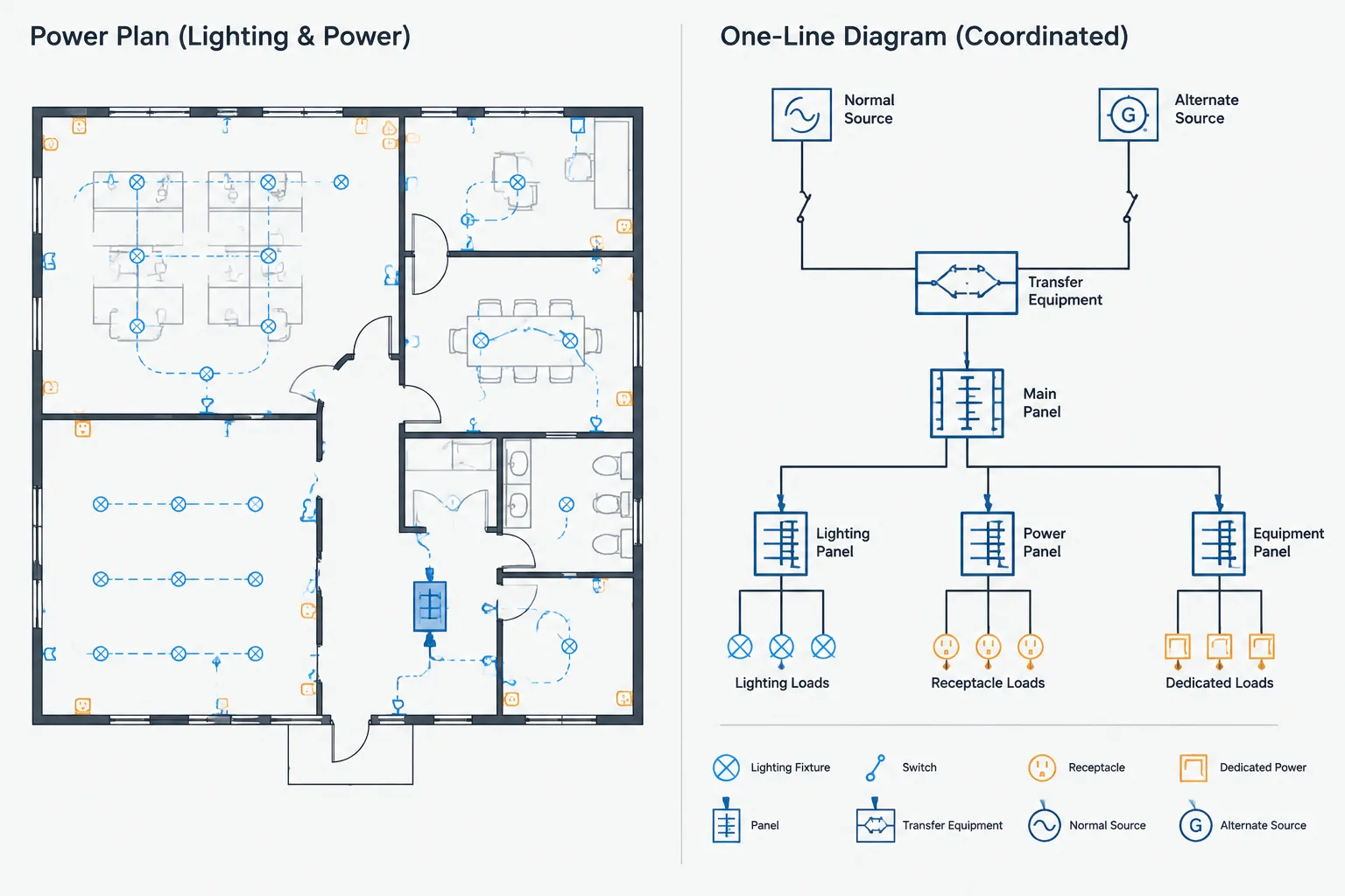
The riser should act as a system map. Equipment and circuit designations shown on the plans should be traceable to it. If a floor plan introduces a remote panel, interface cabinet, or circuit group that does not appear on the riser, the set is incomplete.
The sequence matrix provides another coordination test. Every listed input should be represented by a device, system interface, or clearly defined event. Every output should point to equipment or a documented function. The plan does not need to repeat the full sequence, but its tags and references must support it.
Use graphic status for existing and new work
Renovation drawings require especially clear status control. Existing-to-remain, existing-to-be-removed, relocated, and new devices should not depend only on note wording. Use a coordinated combination of layers, lineweights, symbols, and demolition plans.
A relocated device may need one representation on the demolition plan and another on the new-work plan. Do not leave both visible in the same location without explaining their status. Circuit modifications should also be coordinated so removed devices do not remain in risers or schedules.
Perform a documentation-focused quality check
Before issuing the drawings, review the fire alarm information as a connected set rather than checking each sheet independently.
- Confirm that every symbol used on the plans is defined in the legend.
- Check that device tags are unique where uniqueness is intended.
- Compare panel, circuit, and equipment identifiers across plans, risers, schedules, and matrices.
- Verify that continuation references lead to an actual destination.
- Look for circuit lines hidden behind symbols, notes, or background geometry.
- Check that interface tags match the current mechanical, electrical, and architectural backgrounds.
- Remove abandoned blocks, duplicate symbols, and obsolete revision graphics.
- Plot representative sheets in color and grayscale to test readability.
- Confirm that notes distinguish diagrammatic routing from surveyed or dimensioned routing.
- Flag unresolved placement or system-design questions for qualified review.
Make the CAD file support future revisions
A useful fire alarm CAD plan is not merely clean at the first issue. It should also be maintainable. Use consistent blocks, stable identifiers, controlled layers, and schedules that can be checked against the plan. Avoid exploding symbols or embedding important project data in unsearchable text fragments.
The final drawing set should let a reviewer move logically from a floor-plan device to its tag, circuit relationship, riser location, interface function, and sequence description. That traceability is what turns a collection of fire alarm symbols into coordinated technical documentation.
Leave a Reply
You must be logged in to post a comment.