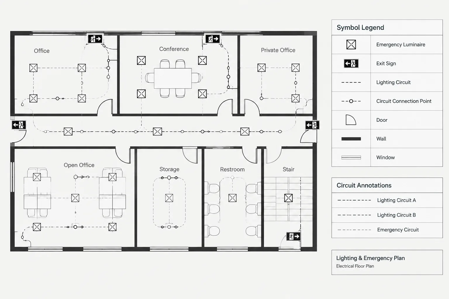
Drafting an emergency lighting plan in CAD requires more than placing recognizable symbols. The drawing must connect each emergency luminaire, exit sign, and supporting device to consistent identifiers, power-source references, control information, schedules, and diagrams.
This guide focuses on the documentation workflow: building a readable symbol system, showing directional intent, coordinating circuit and equipment tags, managing blocks and layers, and checking that information remains consistent across the drawing set. Final system design and compliance decisions must be verified by the responsible design professionals.
An emergency lighting plan is more than a floor plan with a few shaded fixture symbols. It must communicate which luminaires and exit signs serve the emergency function, how they receive power, how normal lighting controls affect them, and where related information appears elsewhere in the drawing set.
The drafter’s task is to make this design intent traceable without crowding the plan. That requires consistent symbols, disciplined circuit annotation, clear source identification, and coordination among lighting plans, panel schedules, control diagrams, single-line diagrams, and equipment schedules. Project requirements and applicable regulations must always be verified by the responsible design team; a CAD symbol or typical detail does not establish compliance by itself.
Define the Emergency Lighting Documentation Strategy
Before placing blocks, determine how the project team intends to document the system. Emergency illumination may be provided by selected luminaires, dedicated emergency fixtures, integral battery units, central battery or inverter equipment, generator-backed distribution, or a combination of methods. Exit signs may have integral backup provisions or may be connected to an emergency distribution system.
The drawings should distinguish these arrangements rather than grouping every device under a generic emergency symbol. Ask the following drafting questions:
- Which fixtures operate during loss of normal power?
- Is the emergency function integral to the fixture or supplied by separate equipment?
- Which panel, inverter, transfer arrangement, or other source serves each device?
- Does a fixture operate normally and transfer to emergency operation, or is it normally off?
- How are local switches, relays, sensors, and lighting control panels represented?
- Which information belongs on the plan, and which belongs in a schedule or diagram?
Resolving these questions early prevents a common problem: a plan that visually identifies emergency fixtures but does not explain their electrical relationship to the distribution and control systems.
Build a Clear Symbol Family
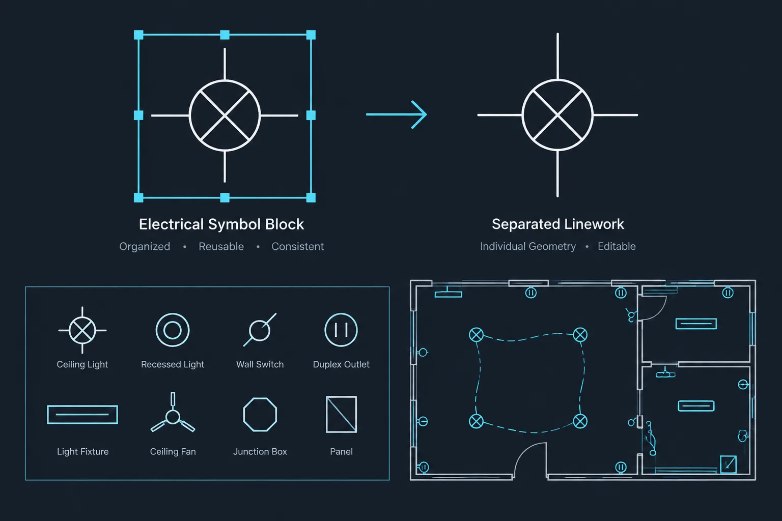
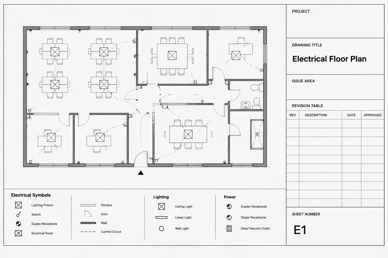
Emergency symbols should remain visually related to the project’s standard lighting symbols. A modifier can identify the emergency function while the base symbol continues to represent the fixture type. Depending on office practice, that modifier might be a fill pattern, boundary, letter, suffix, or separate graphic marker.
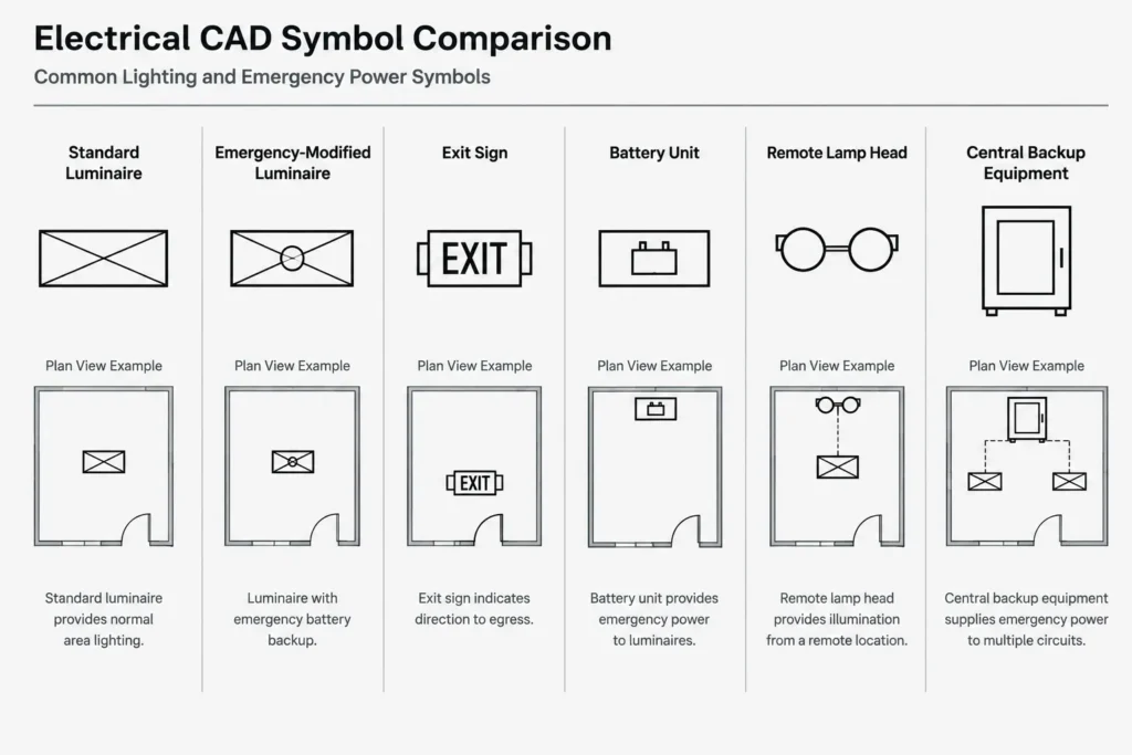
Avoid relying only on color. Colors can disappear in monochrome plots, PDF markups, and printed field sets. The emergency distinction should remain visible through linework, text, or another plot-stable feature.
| Drawing item | Useful CAD distinction | Information to coordinate |
|---|---|---|
| Emergency luminaire | Standard fixture symbol with a consistent emergency modifier | Fixture type, circuit, source, and control behavior |
| Exit sign | Symbol showing sign location and indicated direction where needed | Mounting context, face or direction information, and power source |
| Unit equipment | Dedicated block distinct from a conventional luminaire | Equipment tag, served area, and associated schedule entry |
| Remote lamp head | Directional head symbol connected conceptually to its supplying unit | Parent equipment reference and orientation |
| Central inverter or battery equipment | Equipment outline and tag rather than a fixture symbol | Distribution connections, location, schedules, and diagrams |
Keep the legend limited to symbols that actually appear in the set. If two symbols look similar but represent different backup methods, their descriptions should state that difference directly.
Draft Exit Signs with Directional Intent
An exit sign symbol should communicate more than the presence of a sign. Its placement and orientation must agree with the architectural circulation concept. Where the drawing convention includes directional indication, the arrow or directional component should be readable at the plotted scale and should rotate correctly with the sign.
Use separate block states or carefully managed attributes for sign variations instead of manually adding loose arrows. Loose graphics are easy to leave behind when a sign moves or changes orientation. If the project distinguishes wall-mounted, ceiling-mounted, single-face, or multiple-face signs, preserve those distinctions in the block name, attributes, or schedule data.
Coordinate sign locations with doors, reflected ceiling information, ceiling features, room names, and architectural elevations. A plan symbol may look correct in isolation while conflicting with a bulkhead, glazing system, ceiling transition, or door swing shown by another discipline.
Show Power Sources Without Overloading the Plan
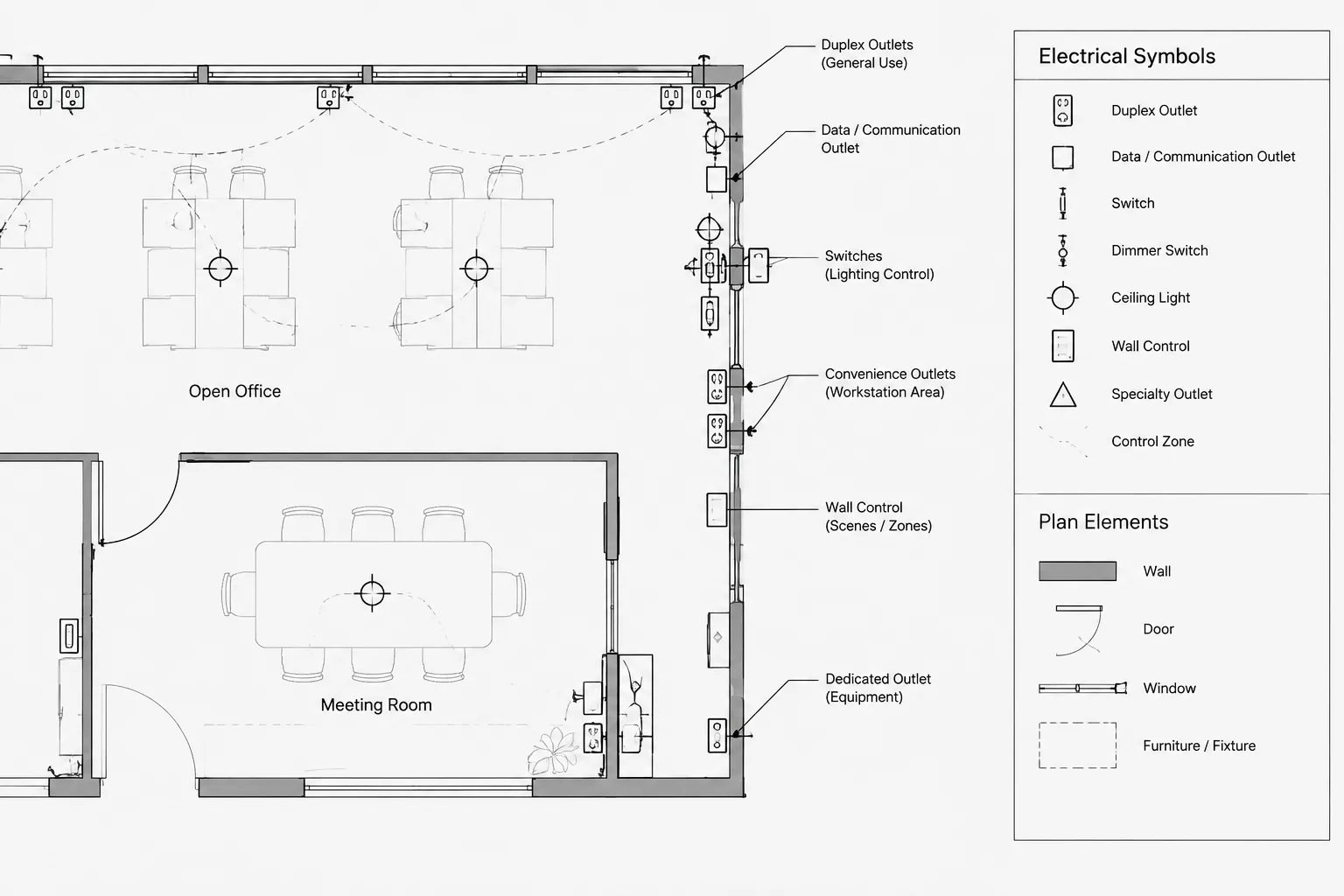
Each emergency device should be traceable to its source, but the floor plan does not need to reproduce the entire distribution diagram. Use concise circuit annotation and references that connect the plan to the appropriate panel schedule, equipment schedule, or diagram.
A practical plan annotation may include the fixture type, circuit designation, and an emergency source or system identifier. The exact format should match the project’s general lighting annotation method. Avoid creating an unrelated tagging system only for emergency fixtures unless the added distinction has a clear purpose.
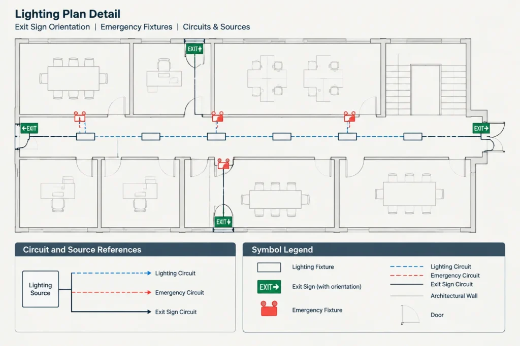
Where a group of fixtures shares the same source and control arrangement, a keyed note or bounded area note may be cleaner than repeating a long description beside every symbol. However, grouped notes must have an unmistakable scope. Readers should not have to guess whether a note applies to one fixture, one room, or an entire plan area.
Coordinate Distribution References
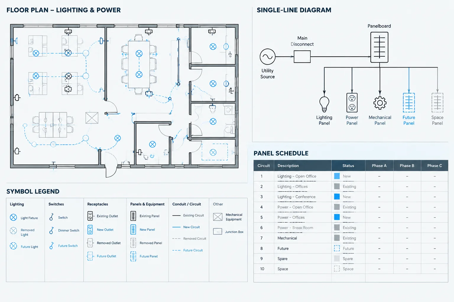
If emergency power is represented on a single-line or riser diagram, use the same equipment and panel identifiers on the lighting plan. A panel should not appear under one abbreviation on the plan and another in the diagram. Likewise, central lighting backup equipment should carry one stable tag across plans, schedules, diagrams, and details.
Document Control Behavior
Emergency luminaires often participate in the normal lighting environment while also requiring defined behavior during a loss of normal power. The drawings must explain that relationship without implying unsupported control logic.
Identify whether an emergency-designated luminaire is normally switched, normally unswitched, controlled through a listed interface selected by the design team, or dedicated to emergency operation. When the logic is too complex for a floor-plan circuit line, reference a lighting control diagram or sequence note.
Control documentation should coordinate the following:
- Local switches, sensors, relays, and control zones shown on the plan
- Normal and emergency source relationships shown in diagrams
- Fixture and control-device identifiers used in schedules
- Any bypass, transfer, or override function defined by the electrical design
- The intended state of affected luminaires during normal and emergency conditions
Do not use a circuit line alone to imply control behavior. Circuiting and control are related, but they are not the same information.
Use Layers and Blocks That Support Revision
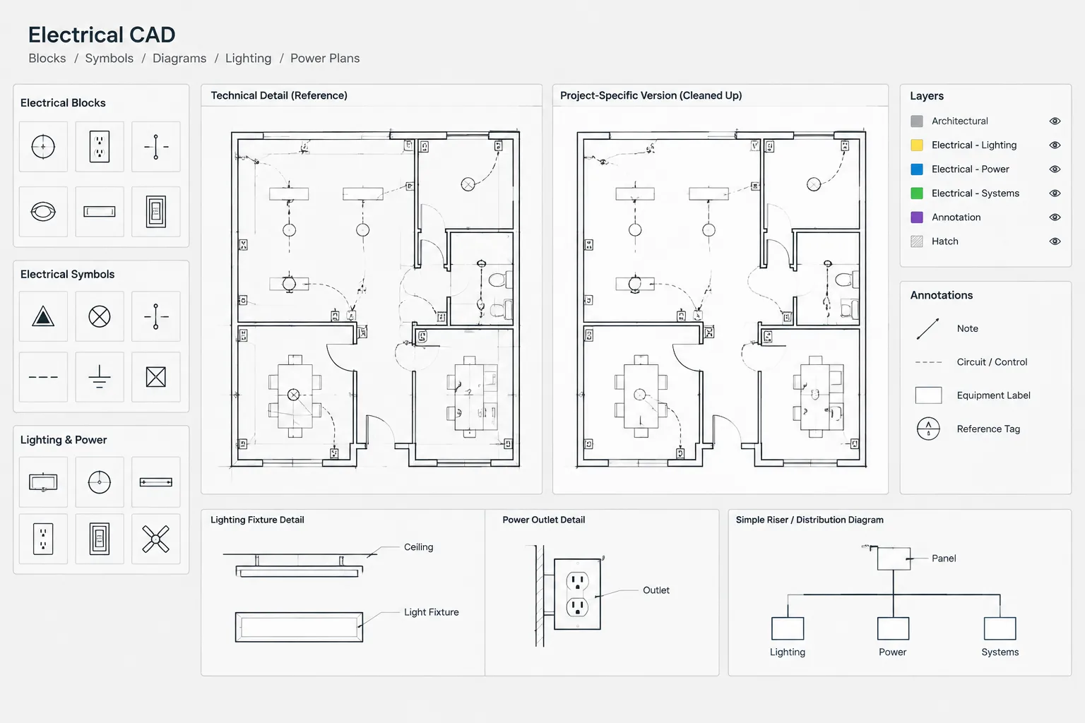
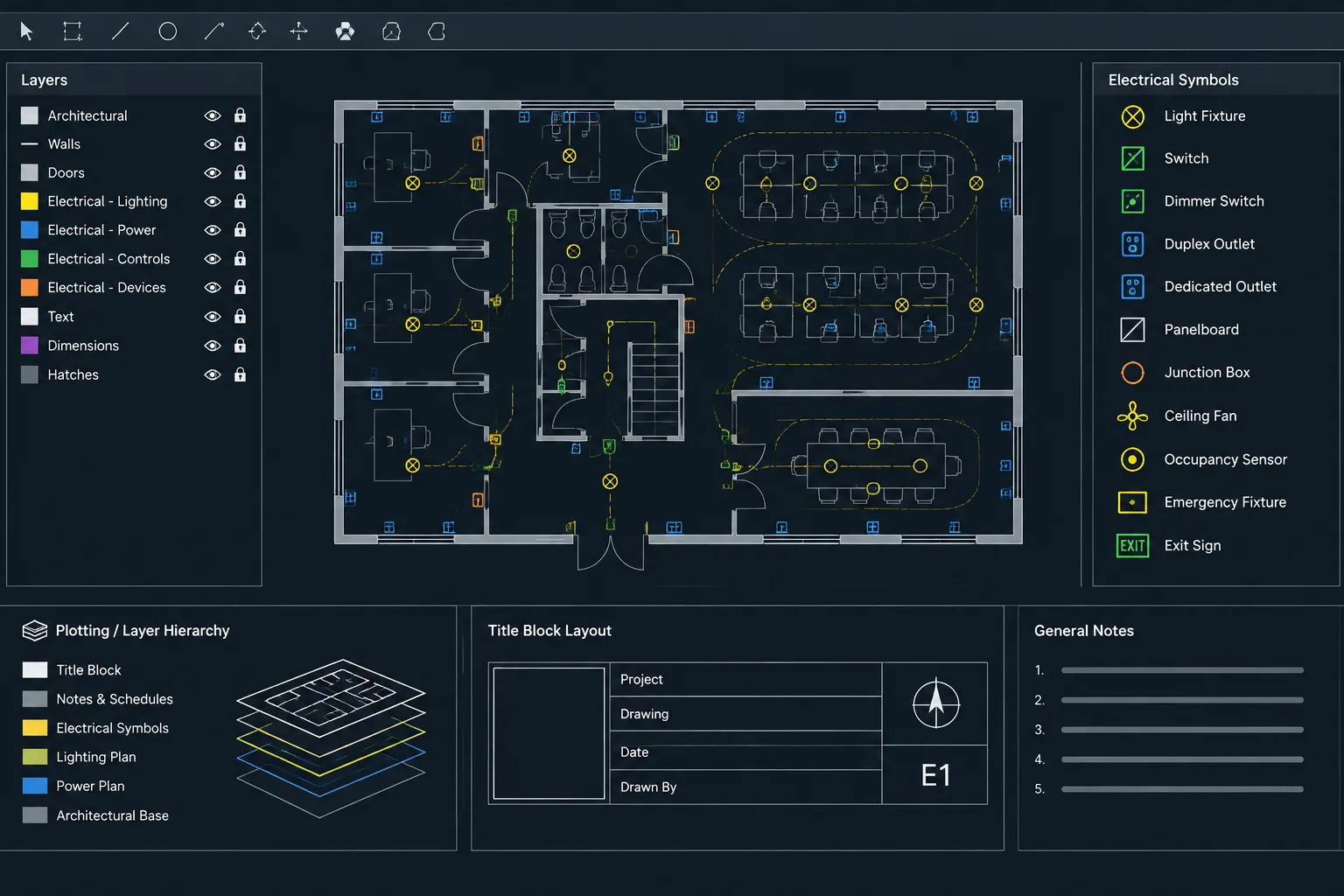
Emergency lighting graphics should fit the project’s broader CAD layer structure. Separate layers may be useful for fixtures, exit signs, circuiting, control lines, equipment, tags, and notes. The exact layer names should follow the project CAD standard rather than an improvised naming scheme.
Blocks should use a consistent insertion point and include only the geometry needed for the intended drawing scale. Attributes can hold fixture types, equipment tags, circuit references, or source identifiers, but visible text should not duplicate nearby annotations unnecessarily.
If symbols are extracted into schedules, define which attribute is authoritative. For example, a fixture type stored in the block should agree with the visible tag and schedule row. Unmanaged duplicate text creates opportunities for conflicting information after revisions.
Coordinate Across the Drawing Set
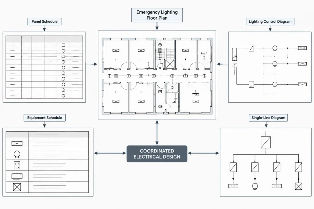
Emergency lighting information commonly appears in several locations. Review it as a connected documentation system rather than checking each sheet independently.
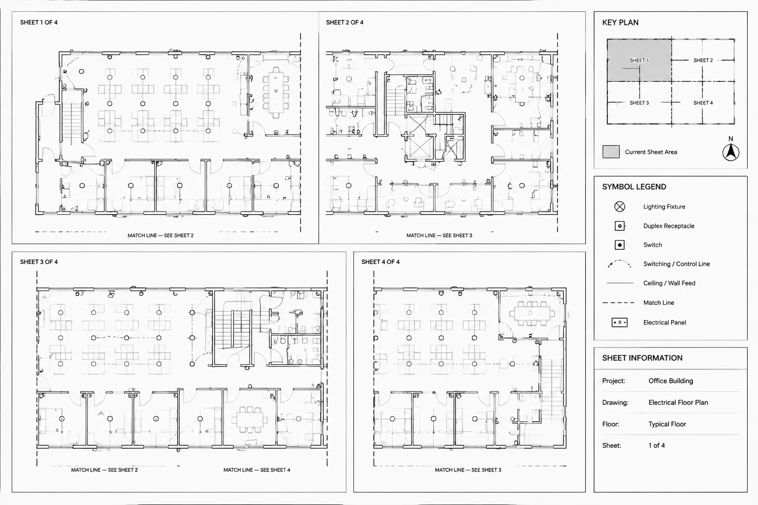
- Lighting plans: Confirm device locations, fixture types, circuit tags, directional graphics, and control associations.
- Reflected ceiling plans: Check ceiling geometry, mounting context, and conflicts with architectural or mechanical elements.
- Panel schedules: Confirm that referenced circuits and panel names exist and use matching terminology.
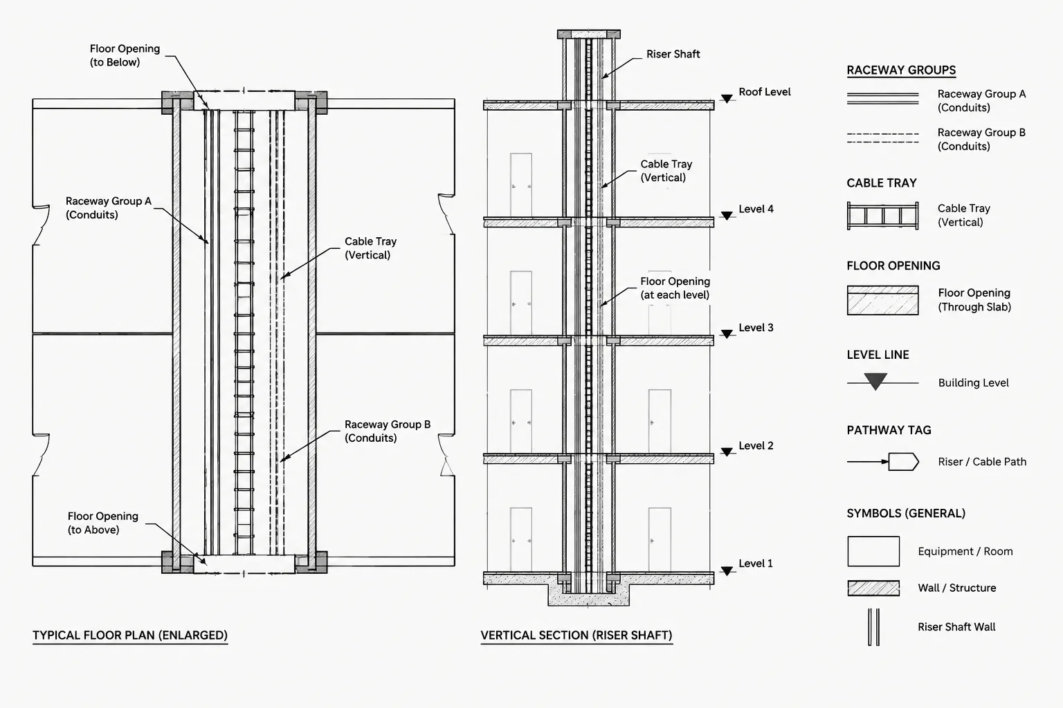
- Single-line or riser diagrams: Verify that emergency distribution paths and equipment identifiers support the plan references.
- Fixture schedules: Coordinate fixture types and descriptions without assuming that a catalog designation alone explains emergency operation.
- Control diagrams: Confirm normal switching and emergency response intent.
- Equipment layouts: Show central backup equipment where required for spatial coordination.
Perform a Focused CAD Quality Check
Before issue, isolate emergency lighting layers or use a dedicated review view. This makes omissions and inconsistent symbols easier to detect. Review every area against the architectural circulation plan and compare plan annotations with schedules and diagrams.
- Are all emergency symbols defined in the legend?
- Do exit sign orientations agree with the intended circulation direction?
- Can every emergency fixture and sign be traced to a documented source?
- Are equipment and panel tags identical across all drawings?
- Are normal control behavior and emergency behavior distinguishable?
- Do emergency modifiers remain readable in monochrome plots?
- Have deleted or relocated fixtures left behind circuit lines, arrows, tags, or control graphics?
- Are keyed notes clearly bounded and referenced?
- Do schedules contain all types and equipment tags used on the plans?
A strong emergency lighting plan does not attempt to place every technical explanation beside every fixture. Instead, it creates a dependable chain of information: the plan identifies the device and location, annotations identify its source and function, and coordinated schedules and diagrams explain the broader system. That traceability is what turns a collection of CAD symbols into useful construction documentation.
Manage Revisions as Connected Drawing Changes
An emergency lighting revision rarely affects only the symbol that moved. Relocating a luminaire or exit sign may also affect circuit annotations, directional graphics, keyed notes, control associations, schedule entries, and references to distribution equipment. Treat the revision as a connected documentation change rather than an isolated plan edit.
When reviewing revised backgrounds or design markups, use a repeatable comparison process:
- Identify added, removed, relocated, and reoriented devices.
- Check whether associated tags, arrows, circuit lines, and control graphics moved with each device.
- Compare block attributes with visible annotations and schedule data.
- Confirm that equipment and panel identifiers still match diagrams and schedules.
- Plot or publish a review copy to verify lineweights, symbol modifiers, and text readability outside the CAD editing environment.
Prepare the File for Team Handoff
Before handing the drawing to another drafter or reviewer, remove abandoned graphics and make the source of each annotation clear. Avoid unexplained text overrides, detached directional arrows, and duplicate tags that appear correct visually but are no longer associated with the intended block.
If external references are used, confirm that the emergency lighting information aligns with the current architectural and reflected ceiling backgrounds. A clean handoff should allow another team member to determine what each symbol represents, where its supporting information is located, and which item must be updated when the design changes.
Separate Drafting Completeness from Design Approval
A coordinated CAD file can demonstrate documentation completeness, but it does not independently prove that device locations, illumination performance, equipment selection, power arrangements, or control behavior satisfy project requirements. The drawing team should flag missing or conflicting information rather than resolving design questions through assumptions.
Useful review comments identify the exact documentation gap, such as an unmatched source tag, an undefined symbol modifier, a sign with unclear orientation, or a fixture that appears on the plan but not in the schedule. This gives the responsible designer a specific issue to resolve while preserving a clear boundary between drafting coordination and engineering judgment.
Frequently Asked Questions
Should emergency fixtures use completely different CAD symbols?
Not necessarily. A standard fixture symbol with a consistent, plot-stable emergency modifier can preserve the relationship to the fixture schedule while clearly identifying the emergency function. The chosen convention should be defined in the legend and used consistently.
Can color alone identify emergency lighting?
Color can support screen-based review, but it should not be the only distinction. Use linework, text, a marker, or another feature that remains visible in monochrome plots and exported documents.
What information should appear beside an emergency luminaire?
Show only the information needed to trace the device within the drawing set, using the project’s established annotation method. Fixture type, circuit reference, source identifier, or a keyed note may be appropriate when defined by the design team. Detailed system relationships can be referenced to schedules or diagrams.
How should directional exit sign variations be managed?
Use controlled block states or managed attributes so the sign and its directional component remain together during rotation, relocation, and revision. The displayed direction should be coordinated with the architectural circulation concept.
Does an emergency symbol establish code compliance?
No. A symbol communicates documented design intent. Compliance depends on the complete design, applicable requirements, equipment selection, installation conditions, and professional verification.
What is the difference between circuiting and control information?
Circuiting identifies an electrical source relationship, while control information describes how a device is switched or responds under defined conditions. A circuit line by itself should not be treated as a complete description of control behavior.
What should be checked after an emergency device is relocated?
Review its orientation, circuit annotation, source reference, control association, keyed notes, schedule data, and any remaining graphics at the previous location. Also compare the revised placement with current architectural and ceiling backgrounds.


Leave a Reply
You must be logged in to post a comment.