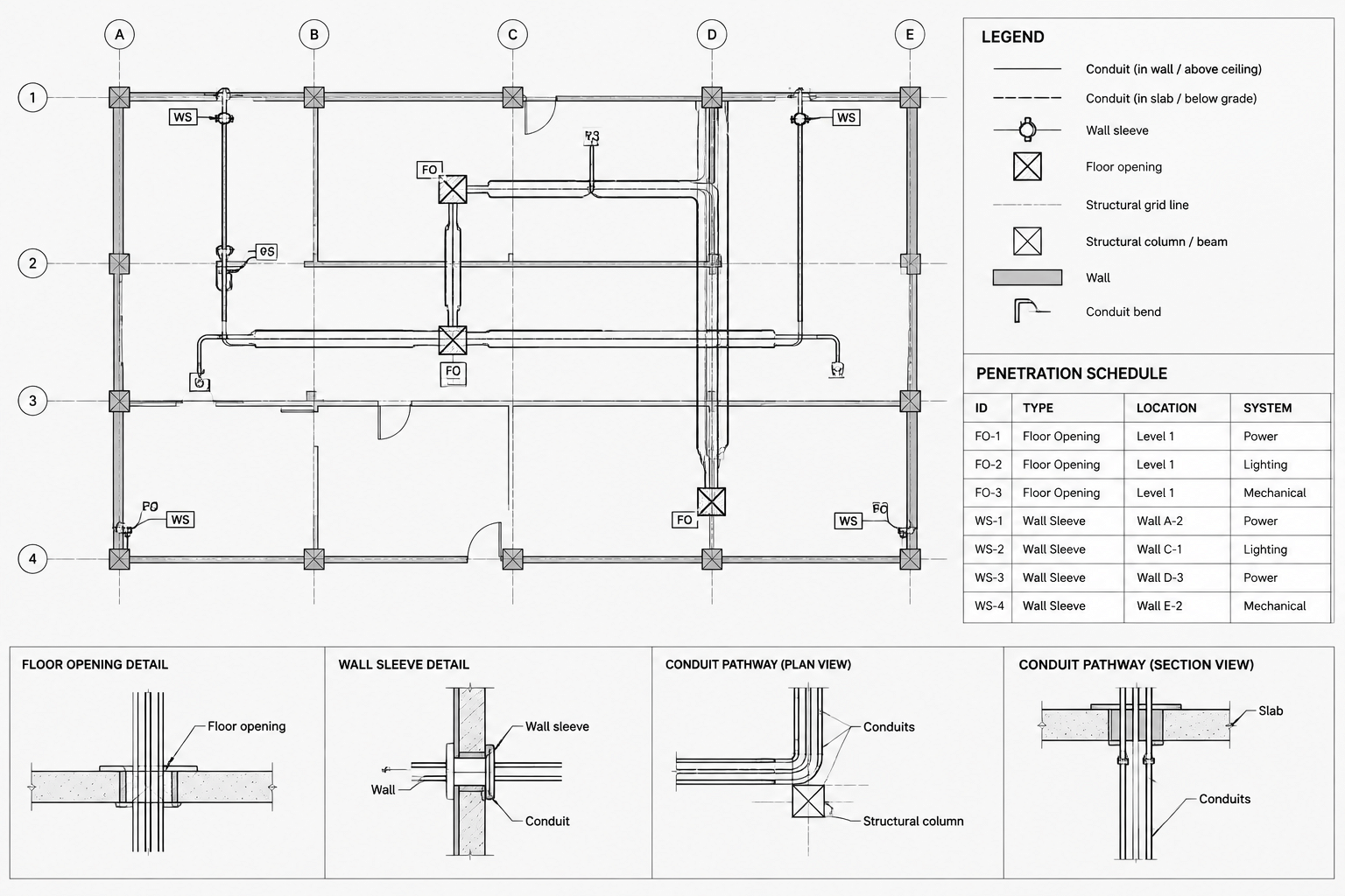
Electrical penetration drawings translate cable and conduit routing intent into coordinated openings through walls, floors, roofs, and other building elements. They help the electrical team communicate where pathways cross construction assemblies, while giving architectural, structural, mechanical, and construction teams a common reference for review.
These drawings are not simply copies of the electrical power plan with circles added around conduit routes. A useful penetration package identifies each opening, shows what passes through it, references the relevant building element, and records whether its location and size have been verified. The drawing should also distinguish design intent from information that must be confirmed through product data, delegated design, field conditions, or another discipline’s requirements.
What an Electrical Penetration Drawing Communicates
A penetration drawing focuses on interfaces between electrical pathways and the building. Depending on the project, it may document sleeves, grouped conduit openings, cable tray crossings, busway penetrations, floor openings, blockouts, or reserved pathway zones.
The drawing should answer several practical coordination questions:
- Where does the pathway cross the wall, slab, roof, or structural element?
- Is the crossing shown in plan, section, elevation, or a referenced detail?
- What electrical system or pathway uses the opening?
- Is the opening intended for one raceway, a group of raceways, or a larger pathway?
- Which team must review the proposed location?
- Has the opening been coordinated, revised, released, or left for confirmation?
A penetration drawing does not, by itself, establish that an opening is structurally acceptable or that a sealing system is suitable for a particular assembly. Those determinations require project-specific review and verified construction information.
Separate Penetration Information from General Electrical Plans
On a simple project, penetration callouts may be incorporated into enlarged electrical plans. On a complex project, dedicated penetration or sleeve plans are usually easier to review. A separate drawing allows the drafter to suppress unrelated devices, circuit graphics, and annotations that would obscure opening locations.
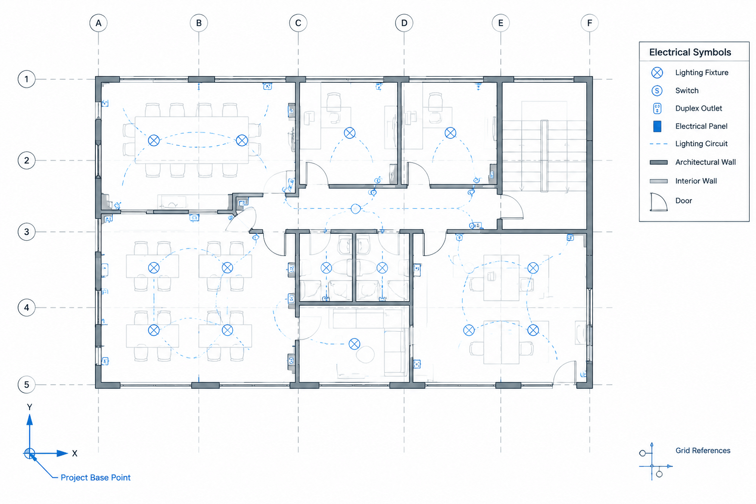
Use the architectural or structural background that best represents the construction being penetrated. A floor plan may show wall crossings clearly, while a structural plan may be more useful for slab openings and relationships to framing. If different backgrounds are required, state which background controls the location and coordinate changes between them.
Do not trace important building geometry into the electrical file unless the project workflow specifically requires it. Referenced backgrounds make changes easier to identify and reduce the risk that obsolete wall or framing information remains embedded in the penetration plan.
Build a Clear Graphic System
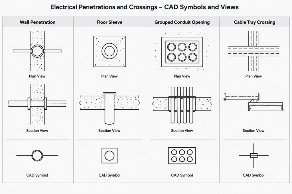
The graphic system should make penetrations visible without suggesting more precision than the available information supports. Penetration symbols need to remain distinct from receptacles, junction boxes, pull boxes, floor boxes, and equipment connection points.
Use Symbols That Match the View
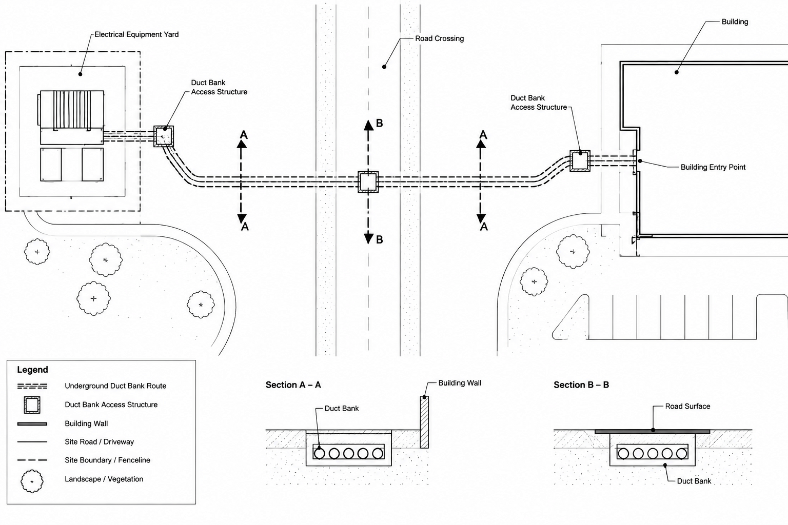
A plan symbol can represent the center or extents of an opening through a floor. A wall penetration may need a marker in plan plus an elevation or section reference. Openings with irregular shapes, multiple pathways, or close relationships to structure often require an enlarged view.
Typical graphic components include:
- An opening or sleeve outline on a dedicated layer
- A center mark or controlled insertion point
- A unique penetration identifier
- A leader connecting the tag to the correct opening
- A direction indicator where the crossing orientation is not obvious
- A section, elevation, or detail reference when plan information is insufficient
Avoid using one generic symbol for every condition. At minimum, the drawing should allow reviewers to distinguish a wall crossing from a floor opening and a single pathway from a grouped opening.
Control Layering and Display
Place penetration outlines, tags, status graphics, and reference geometry on logical layers. This permits the penetration package to be plotted independently and lets coordinators isolate proposed openings during review.
Status should not depend on color alone because drawings may be printed in monochrome. Combine color with text, linetype, hatch, or a separate status field. Existing, proposed, relocated, and removed openings must remain understandable on the issued sheet.
Assign Stable Penetration Identifiers
Each coordinated opening should receive a unique identifier that remains stable through revisions whenever possible. The identifier connects the plan symbol to a penetration schedule, model issue, coordination comment, or field layout document.
A useful naming system may incorporate the floor or area, the opening category, and a unique sequence. The exact convention is less important than consistency. Do not encode changing properties, such as coordination status, directly into the permanent identifier. If the status changes, update a schedule field rather than renaming the opening throughout the drawing set.
For grouped pathways, decide whether the identifier applies to the overall opening or to each sleeve within the group. Show that relationship clearly so that schedule quantities cannot be interpreted in more than one way.
Create a Penetration Schedule
A schedule turns plan markers into reviewable records. Its fields should reflect the project’s actual coordination needs rather than copying an unrelated template.
| Suggested field | Documentation purpose |
|---|---|
| Penetration ID | Connects the schedule entry to the plan marker and related views. |
| Level or area | Helps users locate the opening within the drawing set. |
| Host element | Identifies whether the crossing involves a wall, floor, roof, or other assembly. |
| Pathway description | Summarizes the conduit, tray, busway, or reserved route using the opening. |
| Opening form | Distinguishes a sleeve, grouped sleeves, blockout, or other documented condition. |
| Size reference | Records a verified dimension or directs the reader to a detail or approved source. |
| Location reference | Points to controlled dimensions, grids, elevations, or coordinated geometry. |
| Coordination status | Indicates whether the item is proposed, under review, coordinated, or revised. |
| Remarks | Records constraints, responsible-party notes, or required follow-up. |
If dimensions have not been verified, do not populate the schedule with assumed values merely to complete the table. Mark the information for confirmation and identify the source expected to provide it.
Locate Openings from Stable References
Penetrations should be located from stable project references rather than movable furniture, finish patterns, or temporary equipment graphics. Appropriate references may include structural grids, established wall faces, column lines, slab edges, or other controlled geometry.
Use dimensions selectively. A dense network of dimensions can make a coordination drawing difficult to maintain. Where the workflow relies on coordinated digital models or survey points, the sheet should still provide enough context for a reviewer to understand the location and orientation.
Vertical information is especially important. A plan marker may locate a wall penetration horizontally but fail to show its elevation. Add an elevation value, section, or referenced detail when the vertical position affects routing or coordination. Clearly identify the datum used by the project rather than leaving elevation interpretation to the reader.
Coordinate with Building Assemblies and Other Systems
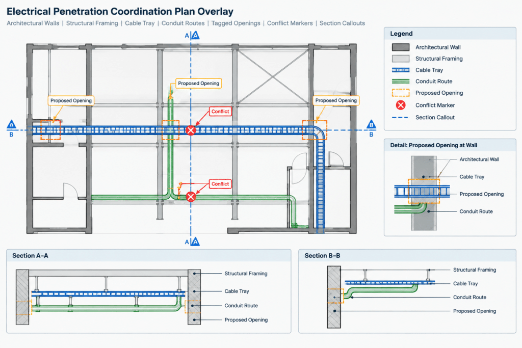
Before an opening is treated as coordinated, compare it with architectural assemblies, structural framing, equipment clearances, access zones, mechanical and plumbing routes, ceiling conditions, and other electrical pathways. Also check whether the host element changes between the plan, section, and detail views.
Rated assemblies and weather-exposed boundaries require particular documentation care. The electrical drawing may identify the crossing and pathway, but it should not casually prescribe a proprietary sealing or waterproofing solution. Reference verified project details, approved submittals, or the responsible design source where applicable.
Structural elements should never be treated as freely available routing space. If a proposed opening conflicts with framing or falls within an area requiring structural review, flag it explicitly and track the response. Moving the CAD symbol without recording the decision can hide an unresolved coordination issue.
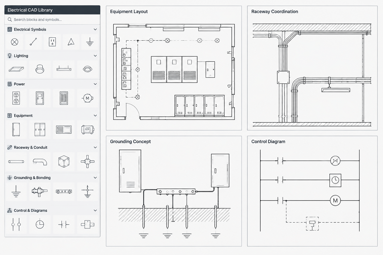
Use Blocks and Attributes Without Losing Context
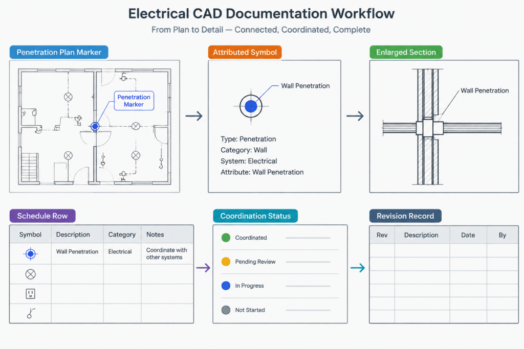
An attributed penetration block can improve consistency by storing the identifier, host type, pathway description, status, and detail reference. Data extraction may then support schedule creation or checking.
Keep visible annotation separate from internal management fields where practical. The plan may need only an identifier and status marker, while the schedule carries the full description. Use a predictable insertion point so that symbol placement represents either the opening center or another clearly defined reference.
Dynamic or adjustable graphics can be useful, but they must not replace verification. Stretching a block to match a drawn opening does not prove that the dimensions are correct or that the opening is acceptable.
Apply a Traceable Coordination Workflow
A disciplined workflow prevents proposed penetrations from being mistaken for approved construction information:
- Collect current architectural, structural, and relevant trade backgrounds.
- Overlay intended electrical pathways and identify each building crossing.
- Create penetration markers and assign stable identifiers.
- Add schedule records with known information and clearly marked unknowns.
- Review locations against framing, equipment, access, and competing services.
- Record comments and decisions without deleting the coordination history prematurely.
- Update plans, enlarged views, sections, schedules, and pathway drawings together.
- Run a final comparison to confirm that every marker has a schedule entry and every schedule entry appears on a drawing.
For revisions, cloud or otherwise identify the affected penetration information according to the project’s document-control procedure. A relocated opening may require updates in several views, not just movement of a plan symbol.
Final CAD Review Checklist
- Symbols are distinct from electrical devices and equipment.
- Every penetration identifier is unique and readable at plotted scale.
- Wall crossings include vertical location information where needed.
- Floor openings are coordinated with the applicable building and structural backgrounds.
- Grouped sleeves and shared openings are represented consistently.
- Unknown dimensions or assembly requirements are clearly marked for verification.
- Plan markers, sections, details, and schedule records agree.
- Status remains understandable in monochrome output.
- Obsolete, relocated, and removed penetrations are handled through the project revision process.
- No note implies structural, fire-resistance, weatherproofing, or installation approval without supporting project documentation.
Well-structured electrical penetration drawings make pathway coordination easier to review and revise. Their value comes from traceable identifiers, stable references, coordinated views, and honest treatment of unverified information—not from filling the sheet with assumed dimensions or generic details.

Leave a Reply
You must be logged in to post a comment.