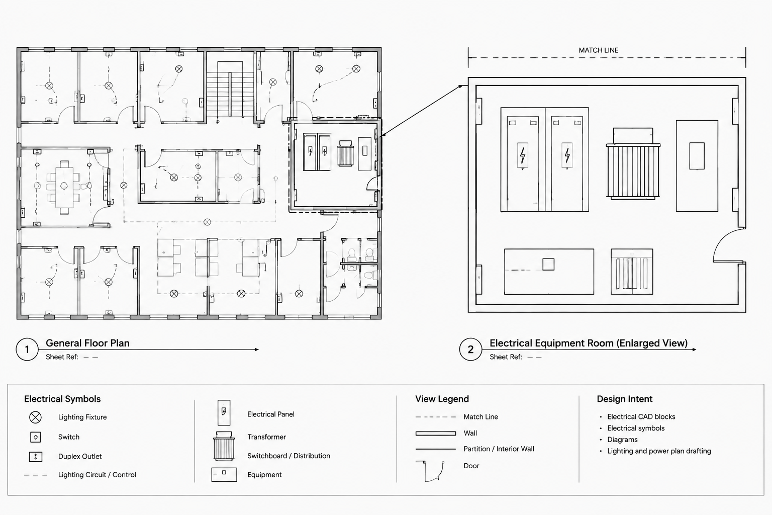
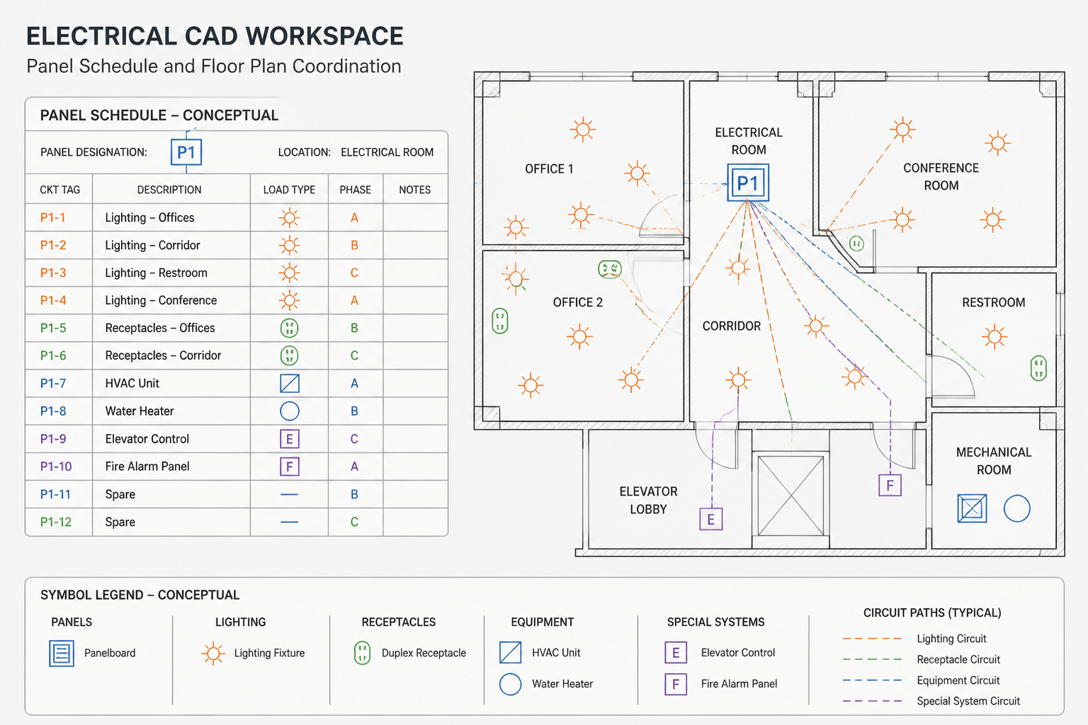
Electrical enlarged plans provide more drawing space for areas that cannot be documented clearly at the scale of a general floor plan. They are commonly used for electrical rooms, dense equipment areas, control stations, service spaces, and locations with overlapping power, lighting, communications, or pathway information.
An enlarged view is not simply a bigger copy of the base plan. It is part of a coordinated drawing system. The general plan must direct readers to the enlarged view, the enlarged view must retain enough context to be understandable, and both views must avoid presenting conflicting information. Match lines, callout symbols, view titles, and continuation references are the drafting tools that make this system work.
When an Electrical Enlarged Plan Is Useful
Consider an enlarged plan when important information becomes difficult to distinguish at the primary floor-plan scale. Typical warning signs include crowded equipment tags, crossing leaders, overlapping circuit annotations, compressed dimensions, or several devices that appear to occupy the same location.
An enlarged view may be appropriate for:
- Electrical and telecommunications rooms
- Generator, transformer, or distribution equipment areas
- Grouped disconnects, starters, and control stations
- Dense receptacle and connection layouts
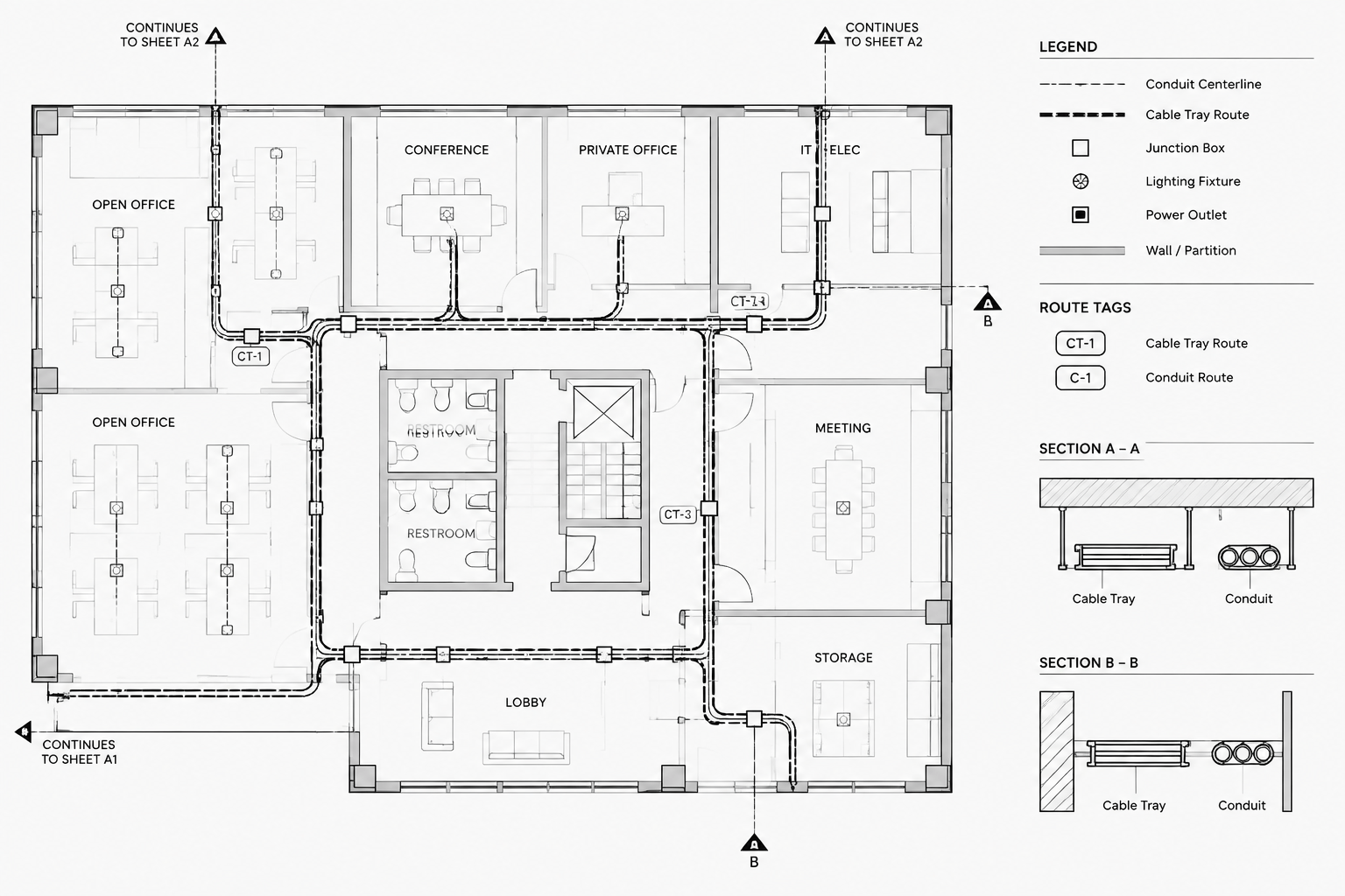
- Areas with several cable tray or conduit routes
- Spaces requiring equipment access or coordination dimensions
- Partial floor plans that continue across multiple sheets
Enlargement should solve a communication problem. Creating extra views without a clear purpose can increase coordination effort and give reviewers more locations to check.
Choose a View Strategy Before Drafting
Decide early how the enlarged plan will relate to the overall plan. The most reliable approach is generally to derive both views from the same coordinated model-space geometry or referenced background. This reduces the risk of walls, doors, equipment, and device locations changing in one view but not the other.
Common view strategies include:
| Strategy | Typical Use | Coordination Concern |
|---|---|---|
| Viewport of shared model geometry | The same CAD information is shown at different plotted scales | Annotation visibility and layer control must be managed carefully |
| Referenced enlarged-plan file | A complex area is developed in a separate discipline file | Reference paths, origin points, and revision responsibility must remain controlled |
| Separate copied geometry | Legacy workflows or special presentation needs | Changes can be missed because the views no longer share a single source |
Copied geometry should be treated cautiously. If a wall, device, or equipment footprint exists independently in two locations, the drafting team must update both whenever the design changes. Shared geometry or managed references usually provide a clearer source of truth.
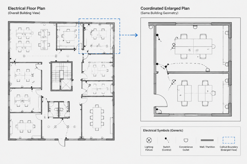
Define the Enlarged View Boundary
The boundary should contain the entire coordination problem, not just the most crowded group of symbols. Include enough surrounding architecture to orient the reader. Nearby doors, wall intersections, room labels, structural features, or major equipment can provide valuable context.
Avoid cutting through the primary equipment group when possible. A view boundary that divides a lineup, pathway, or related group of devices can make design intent harder to follow. If the area must be divided, place the transition in a visually quiet location and provide an unmistakable continuation reference.
Use Crop Boundaries as Presentation Controls
A viewport crop or clipping boundary controls what is displayed; it should not become substitute design geometry. Keep crop objects on a nonplotting or dedicated management layer according to the project CAD standard. This allows drafters to edit the view without accidentally plotting construction rectangles around it.
Review the crop after architectural updates. A shifted wall, expanded room, or relocated equipment group may move outside a boundary that once worked correctly.
Create Clear Plan Callouts
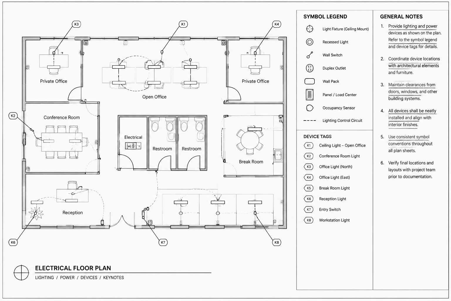
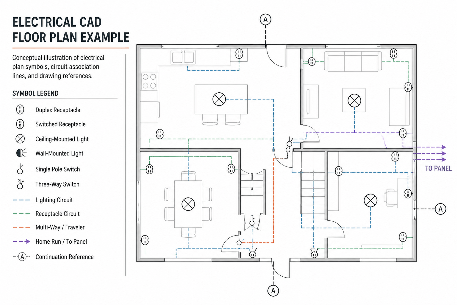
A plan callout tells the reader that another view contains more information. Its graphic form may vary by office or client standard, but it typically combines a boundary or marker with a view identifier and a destination sheet reference.
A useful callout should answer three questions:
- What area is being enlarged?
- What is the enlarged view called?
- Where can that view be found?
Keep the callout visible without allowing it to obscure device symbols, room names, or circuit information. If the project uses an irregular view boundary, make sure the callout still communicates the included area unambiguously.
Callout identifiers should be unique within the drawing set and should agree with the enlarged-plan title. Avoid manually typing the same reference in several unrelated text objects when a managed field or coordinated attribute workflow is available. Regardless of the software method, the visible reference must be checked after views or sheets are moved.
Use Match Lines for Partial and Continuing Plans
A match line indicates where one plan view stops and another continues. It differs from an enlargement callout because it usually connects adjacent portions of the same floor or system rather than directing the reader to a more detailed version of one area.
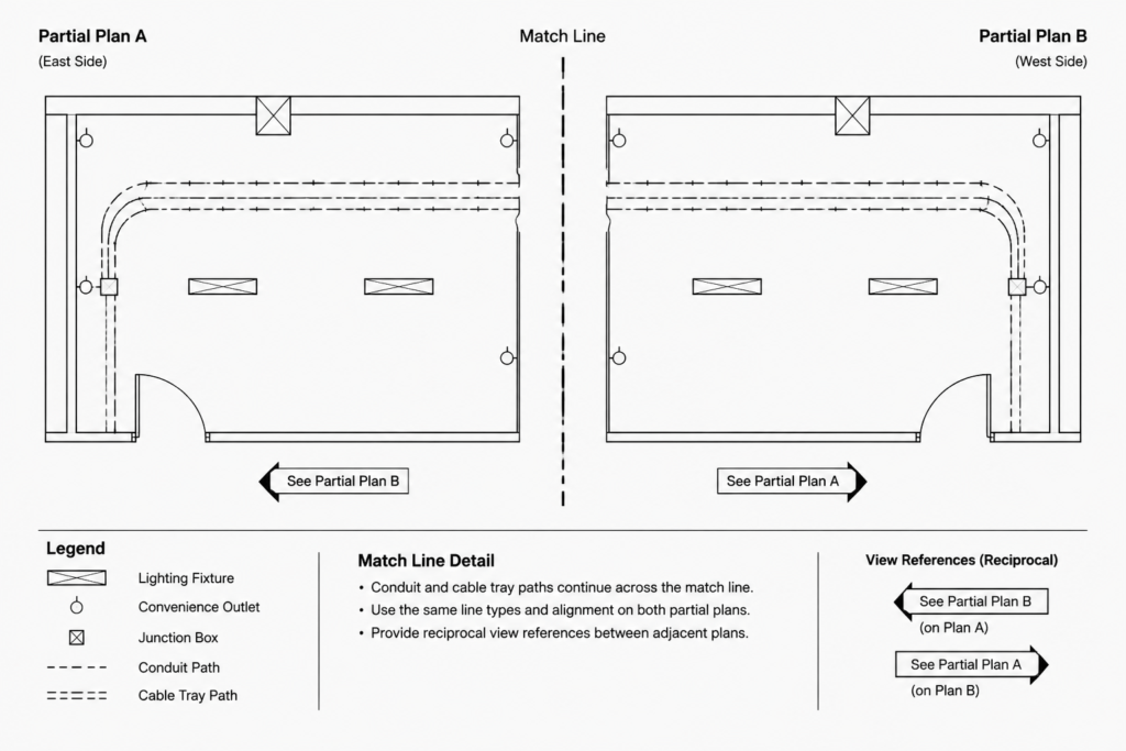
Match lines should be placed where the continuation is easy to understand. Try to avoid running them through important equipment, dense device groups, or complex route intersections. When that cannot be avoided, duplicate only the minimum contextual information needed to make the transition readable.
What a Match-Line Reference Should Communicate
- The direction or area of continuation
- The destination view or sheet
- A consistent graphic distinction from walls and electrical routes
- A clear relationship between the two sides of the break
Both sides of a match line should be reviewed together. A reference that works on one sheet may point to an outdated destination on the other. Readers should not have to guess whether a route, circuit, or equipment connection continues beyond the displayed area.
Control What Appears in Each View
The general plan and enlarged plan should have defined responsibilities. Showing every annotation in both places often creates clutter and increases the chance of disagreement.
A practical hierarchy might keep overall distribution, room coverage, and callout references on the general plan while placing detailed equipment arrangement, local dimensions, connection tags, and dense routing information on the enlarged plan. The exact division depends on the project, but it should be intentional and consistent.
When information appears in both views, determine which view governs and make that relationship clear through notes or drawing conventions. Do not allow duplicated tags or dimensions to develop into two independent instructions.
Manage Annotation for Different Scales
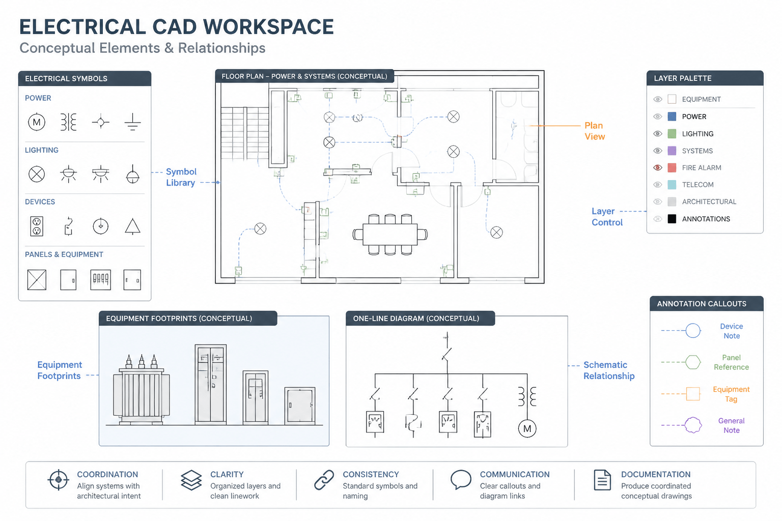
Text, leaders, dimensions, symbols, and linework that read well in an enlarged view may overwhelm the general plan. Use the project’s established annotation method to control visibility and plotted size. Possible methods include dedicated annotation layers, scale-aware objects, viewport-specific layer states, or separate annotation containers.
Regardless of method, inspect the plotted sheets rather than relying only on model-space appearance. Leader crossings, masked areas, clipped labels, and overly dominant symbols are often easier to identify in the final sheet layout.
Coordinate Electrical Information Across Views
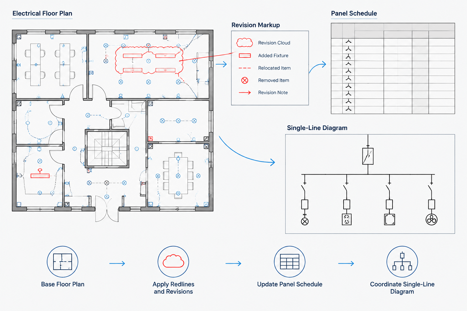
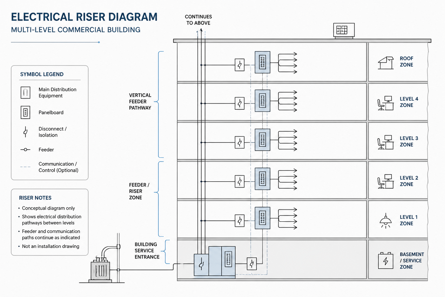
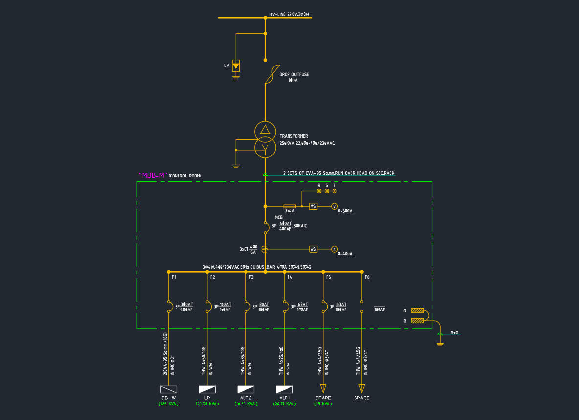
Enlarged plans must remain aligned with related schedules and diagrams. Equipment identifiers should match the single-line or riser diagram, panel names should agree with schedules, and connection tags should use the same terminology throughout the set.
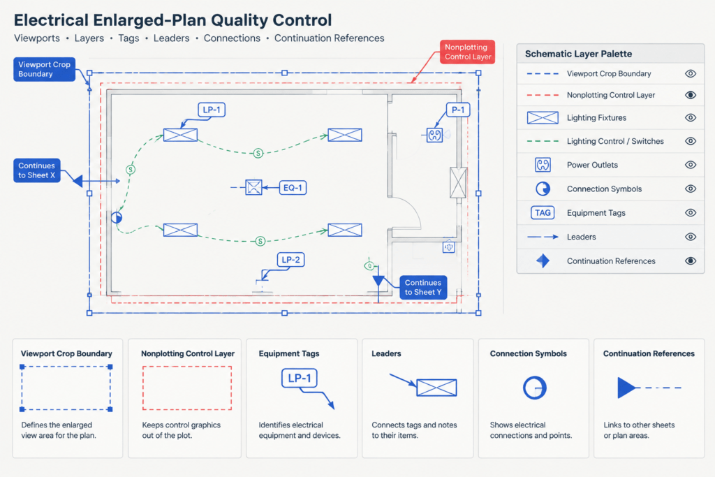
Pay particular attention to information located near the view boundary. Circuit lines, conduit routes, cable tray paths, and feeders need either a visible continuation or a cross-reference. Avoid lines that simply stop at a crop edge without explaining whether they terminate or continue.
Architectural coordination is equally important. Verify that doors, wall ratings represented by the background, equipment pads, access routes, and room names are based on the current referenced files. The enlarged scale can expose background misalignment that is not obvious on the overall plan.
Recommended Layer and Object Practices
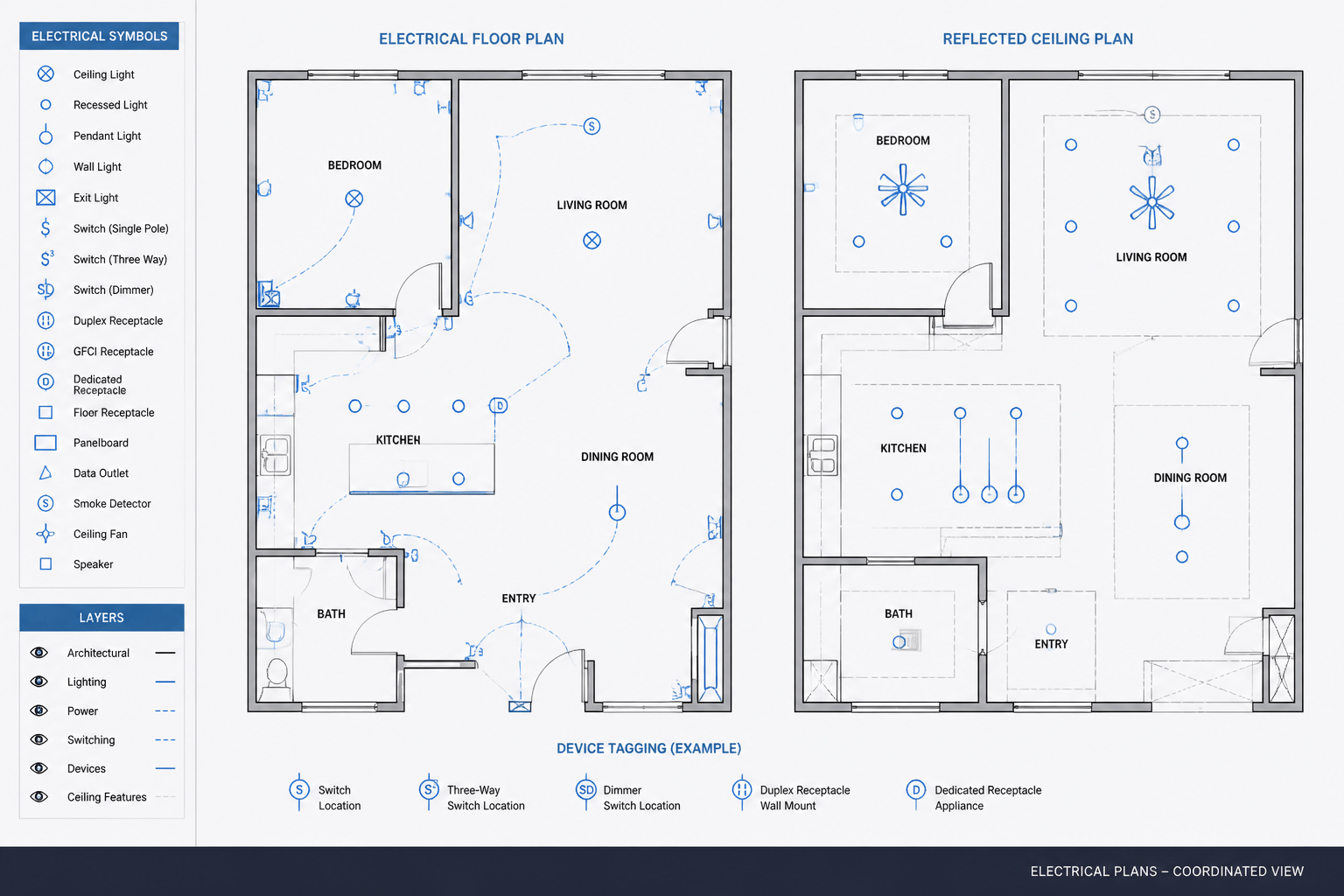
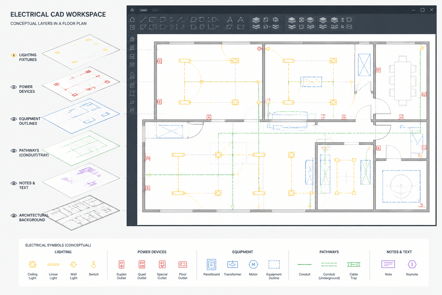
Callouts, match lines, viewport boundaries, and view titles serve different purposes and should be manageable independently. A project may use dedicated layers for each category or group them under a controlled annotation system.
Useful drafting practices include:
- Keeping nonplotting viewport controls separate from visible callout graphics
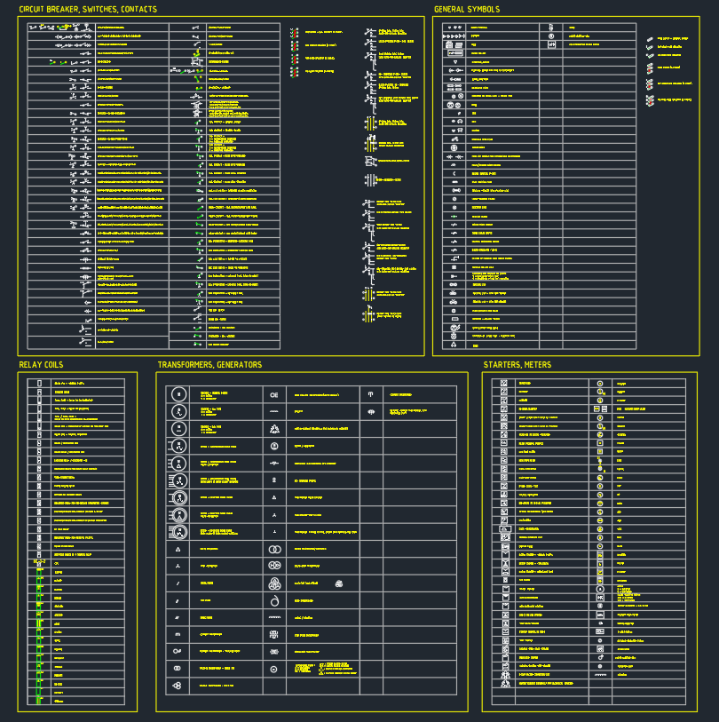
- Using consistent blocks for callout heads and match-line labels
- Storing view and sheet references in editable attributes where practical
- Avoiding exploded callout symbols that lose their formatting consistency
- Separating discipline annotations from referenced architectural text
- Using saved layer states or comparable controls for repeatable viewport display
A downloaded CAD callout or match-line block should be reviewed before use. Check its units, text style, attributes, layers, linework, and plotted appearance against the active project standard.
Quality-Control Checklist
Review enlarged plans and their parent views as a connected group. Before issuing drawings, confirm the following:
- Every enlargement callout points to an existing view and sheet.
- Every enlarged-plan title agrees with its source callout.
- Match-line references work in both directions.
- Routes and circuit graphics do not end unexplained at view boundaries.
- Equipment and device tags agree across plans, diagrams, and schedules.
- Duplicated information is intentional and consistent.
- Crop boundaries remain suitable after background revisions.
- Nonplotting viewport controls do not appear on the issued sheets.
- Text, leaders, and symbols remain legible at the plotted view scale.
- Revision clouds and notes identify the correct view when changes occur.
A Better Enlarged-Plan Workflow
Start with coordinated source geometry, define the information hierarchy, and then establish view boundaries and references. Add detailed annotations only after confirming what belongs on the general plan and what belongs on the enlargement. Finally, review the sheets as a reader would: begin at the overall plan, follow the callout, inspect the enlarged view, and trace any continuation to its destination.
A well-drafted electrical enlarged plan reduces congestion without fragmenting the design narrative. When callouts, match lines, annotations, and shared geometry are managed as one documentation system, users can move through the drawing set with fewer assumptions and less risk of overlooking important information.
Leave a Reply
You must be logged in to post a comment.