
Drafting an electrical control panel layout in CAD requires coordination between physical geometry and the wider drawing set. The enclosure view must communicate where equipment is mounted, while device tags and references connect that arrangement to schematics, wiring documents, terminal information, and material records.
This guide focuses on the documentation decisions that make a panel layout readable, maintainable, and suitable for technical review. It also explains where simplified CAD geometry is useful and where verified equipment information is essential before fabrication.
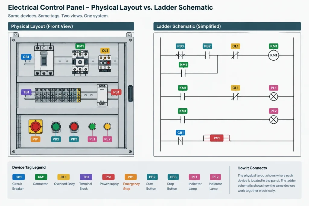
An electrical control panel layout shows the physical arrangement of components inside or on an enclosure. Unlike a schematic, which explains electrical relationships, the layout drawing communicates where devices are located, how they are oriented, and how the assembly is organized for fabrication, wiring, inspection, and future maintenance.
A useful electrical control panel layout CAD drawing must do more than place recognizable blocks inside a rectangle. It should connect physical geometry with device tags, schematic references, terminal information, enclosure details, and equipment documentation. The final arrangement must also be checked against verified manufacturer data and project requirements before it is used for construction or fabrication.
Panel Layout Drawing Versus Electrical Schematic
Control panel documentation often includes several related drawing types. Each answers a different question:
| Drawing type | Primary purpose | Typical information |
|---|---|---|
| Panel layout | Shows physical component arrangement | Enclosure, mounting plate, rails, wireways, devices, terminals, and tags |
| Schematic or ladder diagram | Shows electrical and control relationships | Contacts, coils, power paths, control logic, and cross-references |
| Wiring or connection diagram | Documents conductor connections | Wire identifiers, terminals, plugs, and field connection points |
| Bill of materials | Identifies specified components | Item references, descriptions, quantities, and approved part information |
| External elevation | Shows enclosure-mounted interfaces | Operators, indicators, displays, labels, handles, and openings |
Do not use schematic symbols as substitutes for physical component outlines. A relay symbol may represent its function clearly in a ladder diagram, but the panel layout needs a verified physical footprint or an intentionally simplified envelope identified as diagrammatic.
Start with a Controlled Drawing Framework
Before placing components, establish the drawing basis. Confirm which enclosure, mounting plate, door arrangement, and accessories are part of the design. Use manufacturer information when representing actual equipment. If selections are not final, mark provisional geometry clearly so it cannot be mistaken for verified fabrication data.
The CAD file should have a defined origin and a consistent relationship between the enclosure, mounting surface, and component locations. A predictable reference point makes revisions, exports, and coordination with fabrication data easier. Keep the drawing at a consistent model-space scale and manage sheet presentation through layouts or viewports.
Useful CAD layer groups
- Enclosure: enclosure body, mounting plate, door, panels, and removable covers.
- Mounting hardware: rails, brackets, supports, and related assembly geometry.
- Wire management: wireways, ducts, cable entry areas, and routing corridors.
- Components: breakers, power supplies, relays, controllers, interface modules, and other devices.
- Terminals: terminal strips, grounding terminals, disconnect points, and connector groups.
- Annotation: device tags, item marks, notes, leaders, and location references.
- Clearance or reserved zones: documented access, ventilation, wiring, or future-use areas based on verified requirements.
- Construction aids: centerlines, temporary guides, and nonplotting coordination geometry.
Layer names should follow the project or company CAD standard. The important point is to separate permanent geometry, annotations, routing features, and nonplotting guides so reviewers can isolate information quickly.
Build the Enclosure and Mounting Geometry
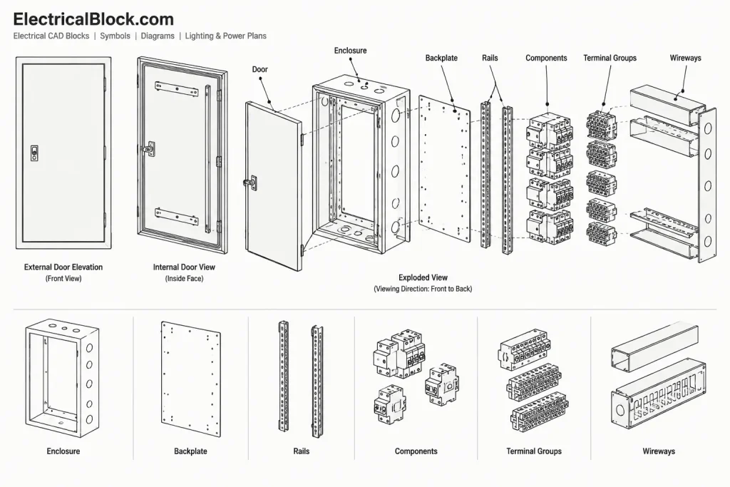
Draft the enclosure outline and mounting plate before arranging devices. Show only the amount of enclosure detail needed for the drawing’s purpose. A fabrication-oriented drawing may require more physical detail than a design-development layout.
Represent door-mounted and backplate-mounted equipment separately. Components on the door can be shown on an external elevation, an internal door view, or both. Clearly identify the viewing direction because a door interior viewed from inside the enclosure may appear reversed relative to the exterior face.
Add mounting rails, wireways, cable-entry regions, and other organizing features as distinct CAD objects or blocks. Avoid exploding reusable assemblies unless editing requires it. Retaining block structure helps maintain consistency when similar panels are created.
Place Components by Function and Connection Flow
A readable layout usually reflects the functional organization of the panel. Incoming power equipment, distribution components, control devices, interface equipment, and field terminals should form understandable groups. The arrangement should help a reviewer trace how power and signals move through the enclosure without implying that visual proximity replaces the schematic.
Consider the following drafting relationships:
- Place incoming and outgoing connection areas where cable entry and field routing can be coordinated.
- Group related control components where practical, while preserving their unique device tags.
- Keep terminal strips visually organized by function or destination when supported by the project documentation.
- Show reserved space as a defined zone rather than an unexplained blank area.
- Coordinate equipment orientation with verified connection locations and manufacturer installation information.
- Identify barriers, partitions, or segregated areas when they are part of the selected assembly.
The CAD layout should not invent spacing, thermal performance, bending allowances, or access requirements. Those conditions depend on the selected equipment, enclosure system, conductor arrangement, and applicable project criteria. Use confirmed design inputs rather than estimating from a generic block.
Create Reliable Component Blocks
Control panel blocks should be simple enough to keep the file manageable but detailed enough to prevent placement errors. Show the physical envelope, mounting relationship, and important connection sides when those details affect coordination. Decorative detail that does not improve layout decisions can make crowded panels harder to review.
Useful block attributes may include:
- Device tag
- Item or material reference
- Component description
- Schematic cross-reference
- Terminal strip or connector designation
- Manufacturer and part information when verified
- Revision or approval status for library management
Keep the visible device tag separate from longer database information when possible. This allows the plotted layout to remain readable while preserving data for schedules or extraction. Dynamic or parametric behavior may be useful, but only when users understand which changes preserve a valid physical representation.
Document Wireways and Routing Intent
A panel layout does not need to draw every conductor to communicate routing intent. Wireways or routing corridors can show how conductors are expected to move between device groups and terminal areas. The schematic and wiring documentation should carry the detailed connection information.
Use clear linework to distinguish wire management products from wires, rails, and enclosure edges. Where routes cross or pass behind equipment, use appropriate hidden-line conventions, breaks, or separate views rather than allowing overlapping geometry to become ambiguous.
Cable entry information should also coordinate with external equipment layouts. If cables enter from above, below, or through a specific enclosure surface, that intent should agree with the room layout, tray or conduit routing, and any related penetration details.
Coordinate Tags Across the Drawing Set
Every tagged device on the panel layout should have a corresponding identity elsewhere in the documentation. A layout tag may connect to a ladder diagram, single-line diagram, terminal plan, connection schedule, or bill of materials.
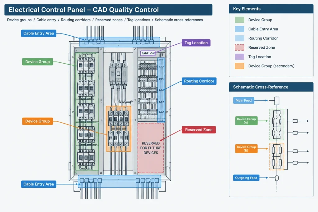
Consistency matters more than visual complexity. The same device should not receive different identifiers simply because it appears in different drawing types. When one assembly contains multiple functional elements, establish how the main device tag and sub-elements will be represented before annotation is added.
Cross-references should be treated as project data, not decorative text. If a schematic sheet or location changes, associated references need to be updated and checked. CAD attributes or project databases can reduce repeated typing, but automated output still requires review.
Use Separate Views for Crowded Information
Trying to show the enclosure, door, mounting plate, terminals, labels, and connection details in one view often produces an unreadable drawing. Divide the information into purposeful views instead.
- Internal arrangement: backplate components, rails, wireways, and terminal strips.
- External door elevation: operator devices, indicators, displays, and labels.
- Internal door view: rear bodies, contact blocks, wiring areas, and door-mounted accessories.
- Side or sectional view: component depth, door conflicts, and mounting relationships.
- Detail view: dense terminal groups, connector panels, or repeated mounting arrangements.
Reference every secondary view from the main layout and label its orientation. This reduces the risk of mirrored door arrangements or misunderstood viewing directions.
Panel Layout Quality-Control Checklist
- Confirm that the enclosure and mounting geometry match verified project information.
- Check that component blocks represent the selected devices or are clearly marked as provisional.
- Compare every device tag with the schematic and material documentation.
- Verify that door-mounted and backplate-mounted items are shown in the correct views.
- Review component orientation and connection sides.
- Check for physical overlaps among devices, rails, wireways, labels, and enclosure features.
- Confirm that cable-entry intent agrees with related plans and routing drawings.
- Make reserved areas and future provisions explicit.
- Remove construction guides from plotted output or place them on nonplotting layers.
- Plot or export a test sheet to review text size, line hierarchy, and tag readability.
Make the Layout Useful Beyond Initial Design
A well-structured electrical control panel layout CAD file can support design review, assembly coordination, field documentation, and later revisions. Its value depends on disciplined relationships between geometry and project data. Reusable blocks, consistent tags, controlled layers, and clear cross-references make the drawing easier to maintain than a collection of disconnected lines and text.
The layout should still be treated as part of a coordinated documentation set rather than a standalone fabrication guarantee. Final component selection, dimensions, mounting instructions, access needs, environmental conditions, and installation requirements must be checked against approved project information and manufacturer documentation.
Plan for Revisions and Drawing Handoff
Panel layouts often change as component selections, enclosure details, and connection requirements are confirmed. A controlled revision workflow helps prevent an outdated footprint, tag, or mounting arrangement from remaining in the drawing after related documents have changed.
Track the Status of Layout Information
Distinguish approved component geometry from provisional envelopes and coordination zones. Status information can be managed through block attributes, layer controls, drawing notes, or the project data system. The method should make uncertainty visible without overwhelming the plotted layout.
When a device changes, review more than its outline. Check its mounting relationship, orientation, connection sides, associated tags, material reference, wireway relationship, and appearance in other views. Replacing a block without reviewing these dependencies can leave the drawing internally inconsistent.
Prepare a Reviewable CAD File
- Use descriptive block and layer names that follow the project CAD convention.
- Remove duplicate geometry and isolate nonplotting construction aids.
- Confirm that external and internal door views have clearly stated viewing directions.
- Keep annotations associated with the correct devices rather than relying on visual proximity.
- Review referenced files, fonts, line types, and plotted output before issuing the drawing.
- Record unresolved selections or provisional geometry in a visible and controlled manner.
Coordinate Changes Across Documents
A revision to the physical layout may affect wiring routes, terminal assignments, enclosure openings, equipment schedules, or schematic references. Conversely, a schematic change may add or remove devices that must be reflected in the enclosure arrangement. Treat the panel layout as one coordinated view of project data rather than an independent CAD sheet.
Before release, compare the current layout against approved manufacturer information and the latest project documents. CAD organization improves review efficiency, but it does not replace engineering evaluation, fabrication checks, or confirmation of installation requirements.
Electrical Control Panel Layout CAD FAQ
Can schematic symbols be used as panel layout blocks?
Schematic symbols describe electrical functions and relationships, not physical size or mounting arrangement. A panel layout should use a verified equipment footprint or a clearly identified provisional envelope.
What should a control panel CAD block show?
A useful block shows the physical envelope, mounting relationship, orientation, and relevant connection sides when they affect coordination. Visible tags and controlled attributes can connect the block to schematic and material information.
How should provisional components be documented?
Place provisional geometry on a controlled layer or assign a clear status through notes or attributes. Reviewers should be able to distinguish an estimated coordination envelope from approved manufacturer geometry.
Why are separate internal and external door views important?
The exterior face communicates operator and label locations, while the interior view shows rear bodies, accessories, and wiring space. Clearly labeled viewing directions help prevent mirrored arrangements and orientation errors.
Should every wire be drawn on the panel layout?
Not necessarily. The layout can document wireways, routing corridors, cable-entry regions, and connection areas while detailed conductor relationships remain in schematics, wiring diagrams, and terminal documentation.
What should be checked after replacing a component block?
Review mounting, orientation, connection sides, tags, material references, adjacent equipment, wireways, and related drawing views. A replacement can affect several documentation relationships even when it appears to fit visually.


Leave a Reply
You must be logged in to post a comment.