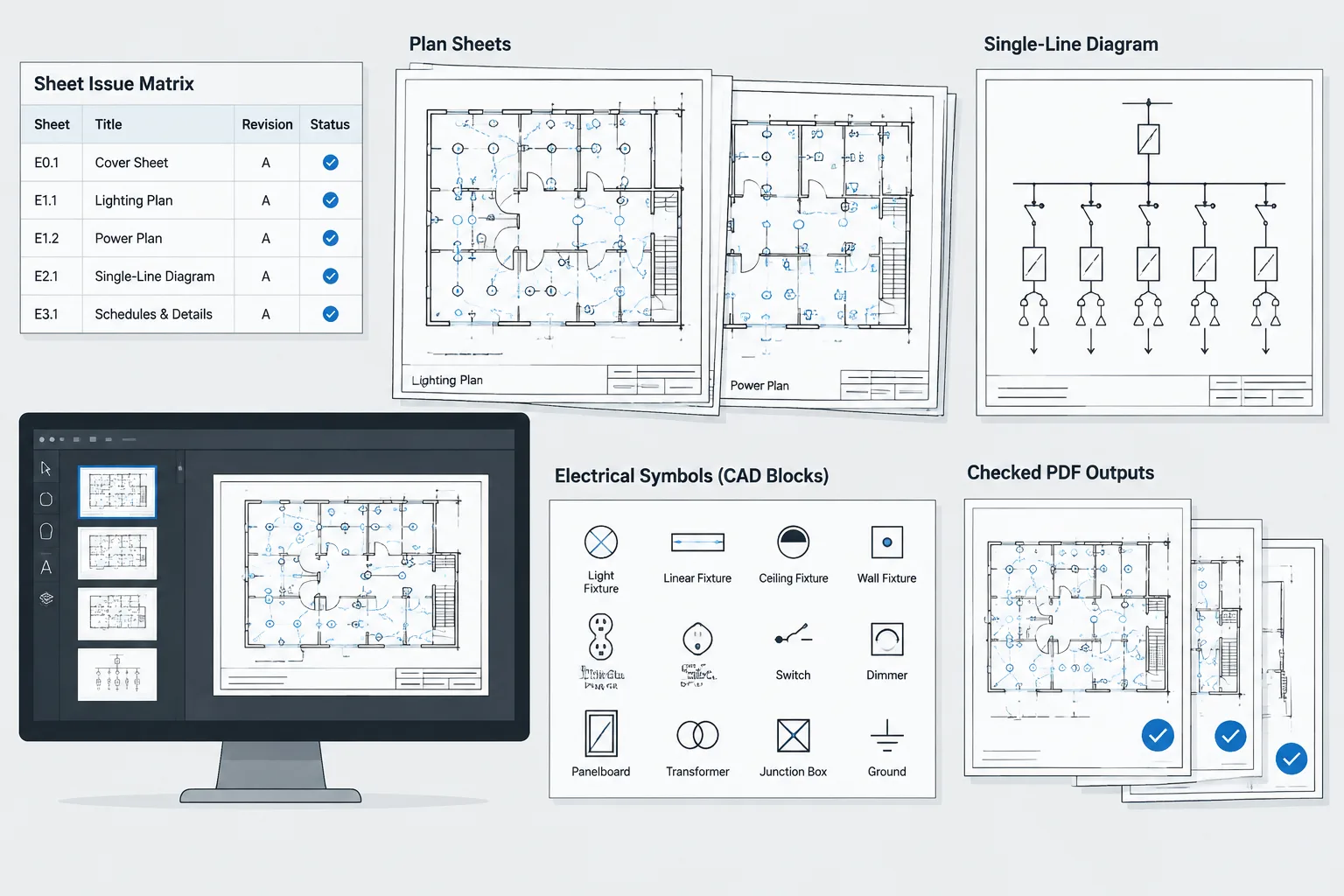
Publishing an electrical drawing set requires more than confirming that every CAD sheet will plot. The release must also represent the intended issue scope, use coordinated source files, and remain traceable after delivery. The following workflow organizes those checks from the initial publishing brief through final output review and archiving.
Use this guidance as a documentation and quality-control framework rather than a substitute for engineering review, contractual requirements, or a project-specific release procedure. The responsible team should adapt each checkpoint to its CAD platform, document-management system, deliverable requirements, and approval structure.
An electrical drawing issue package is more than a collection of plotted sheets. It is a coordinated snapshot of plans, diagrams, schedules, details, and supporting files released for a defined purpose. If even one sheet comes from the wrong revision, contains an unresolved reference, or contradicts another drawing, the package can create avoidable questions and rework.
A reliable pre-publish workflow separates design editing from issue preparation. The goal is not to redesign the project during plotting, but to confirm that the intended information is coordinated, readable, and traceable before it leaves the project team.
Define the issue before publishing
Start by identifying exactly what is being issued. Status terms such as review, bid, permit, construction, addendum, and record may have different contractual meanings from one project to another. Use the terminology established by the project team rather than assuming that a familiar label has a universal definition.
Record the basic issue information in a controlled location:
- Issue purpose or status
- Release date
- Included disciplines and electrical drawing groups
- Sheets added, removed, or replaced
- Revision designation, where applicable
- Required native files, PDFs, or other deliverables
- Person responsible for final package assembly
This information acts as the publishing brief. It helps prevent a common failure: producing a technically clean PDF set that does not match the requested scope.
Separate working files from the issue snapshot
Live CAD files continue to change as coordination progresses. An issue package should represent a stable snapshot rather than a moving target. Establish a clear freeze point for the release, then avoid untracked edits while sheets are being checked and published.
Teams can support this process with a dedicated issue folder, controlled file copies, a document-management state, or another approved project method. The specific system matters less than the ability to identify which files produced the issued sheets.
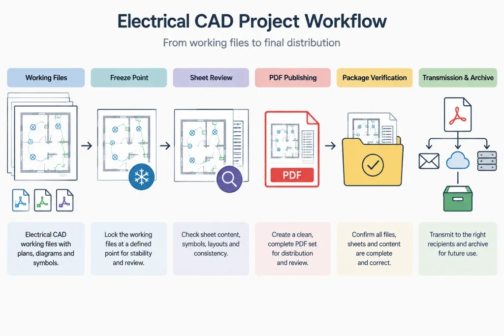
Do not overwrite the only available working model merely to create an archive. Also avoid renaming referenced files without checking how the change affects paths, sheet references, data links, and publishing routines.
Build an issue sheet matrix
A sheet matrix is a practical control document for package assembly. It can be a spreadsheet, drawing table, or managed project list. Each row represents one expected sheet and records its review status.
| Check field | Purpose |
|---|---|
| Sheet number and title | Confirms identity against the drawing index and title block. |
| Source CAD file | Identifies the file used to generate the sheet. |
| Issue status | Confirms that the sheet belongs in the current release. |
| Revision information | Tracks the intended revision designation and description. |
| Plot review | Records whether the published output has been visually checked. |
| Coordination review | Records whether cross-sheet relationships have been checked. |
| Comments | Captures exclusions, approved exceptions, or corrective actions. |
The matrix should distinguish between “not applicable,” “not reviewed,” and “reviewed with no issue.” Leaving cells blank makes it difficult to tell whether a check was intentionally omitted.
Perform sheet-level CAD checks
Review each source sheet before relying on the final PDF. Some problems are easier to diagnose in CAD, especially those involving layers, external references, viewports, annotation scales, or missing resources.
Confirm references and backgrounds
- Verify that required architectural and consultant backgrounds are loaded.
- Look for unresolved, substituted, or unexpectedly duplicated references.
- Confirm that reference visibility is appropriate in each viewport.
- Check that the displayed background revision matches the accepted coordination basis.
- Inspect clipped references near plan boundaries and match lines.
A reference can appear correct on one computer while failing in a transferred package because it was found through an unintended local path. If native CAD files are part of the deliverable, reference portability requires a separate check.
Review viewports and plotted extents
Confirm that every intended viewport is active, properly framed, and using the expected layer visibility. Look for model geometry outside the viewport, clipped notes, accidental viewport shifts, and objects placed directly on top of title-block information.
Do not judge a viewport only by how it looks in model space. The plotted sheet is the governing presentation, including its scale label, title, detail reference, and relationship to surrounding notes.
Check annotation and symbols
Scan for missing fonts, substituted characters, broken fields, unreadable leaders, empty block attributes, and symbols that have lost their intended linework. Confirm that device tags, equipment identifiers, circuit references, and keyed notes remain legible at the published sheet size.
Downloaded or library blocks should be treated as source graphics, not automatically accepted project content. Their layers, attributes, units, insertion behavior, and graphic conventions must be checked before issue.
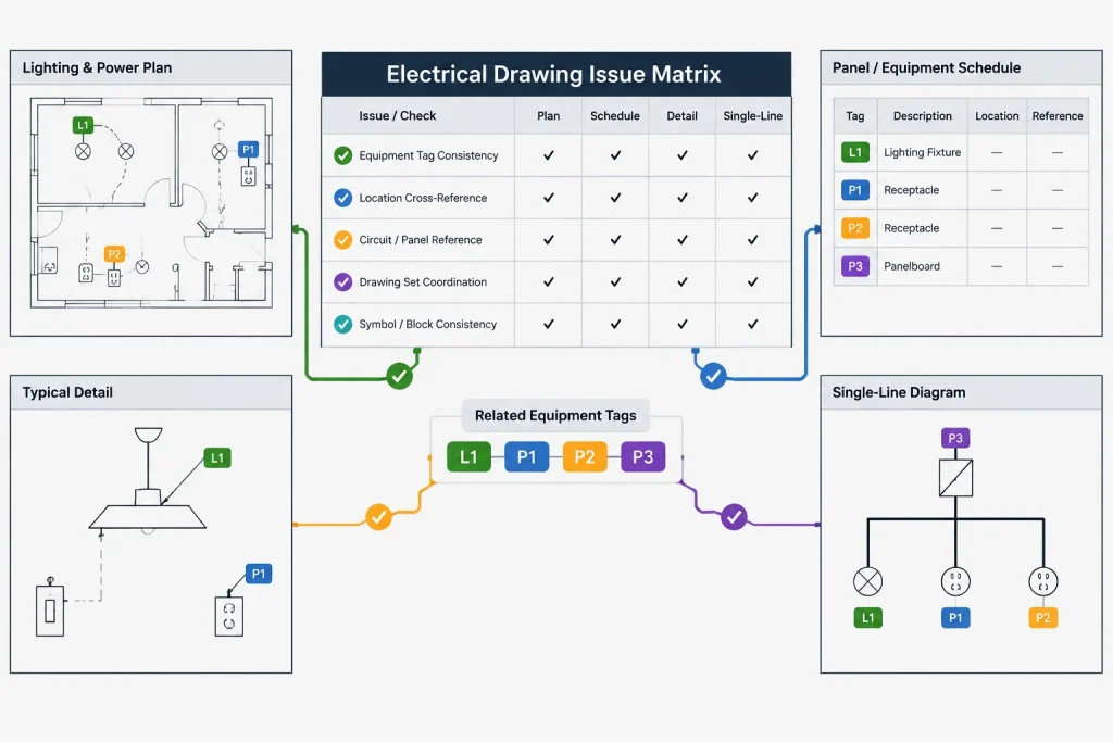
Reconcile information across electrical sheets
A sheet can be internally correct yet conflict with the rest of the set. Package review should therefore include targeted comparisons between related documents.
- Compare equipment tags on plans with one-lines, schedules, and equipment lists.
- Confirm that panel and circuit references used on plans exist in the associated schedules.
- Check feeder and raceway identifiers wherever they continue between plans, risers, or diagrams.
- Verify that detail and section callouts point to sheets included in the package.
- Compare demolition and new-work boundaries where both drawing types are used.
- Confirm that normal, backup, and other project-defined system classifications are shown consistently.
- Review plan continuations at match lines and off-sheet connectors.
This is not a substitute for engineering review. It is a documentation check intended to expose contradictions, incomplete references, and publishing omissions.
Check revision and title-block data
Revision information often appears in several places: the title block, revision history, drawing index, transmittal, and file name. These locations should tell the same story.
Confirm that the current issue designation is visible where the project requires it and that stale revision clouds or tags are handled according to the established documentation procedure. A cloud left from an earlier review can misdirect attention, while a missing revision marker can conceal the intended change.
Also check project name, sheet number, sheet title, issue date, discipline designation, and any project-specific status fields. Attribute-based title blocks reduce repetitive typing, but they do not eliminate the need to inspect the plotted result.
Publish and inspect the actual output
A successful CAD plot command does not prove that the package is correct. Inspect the files that will actually be transmitted.
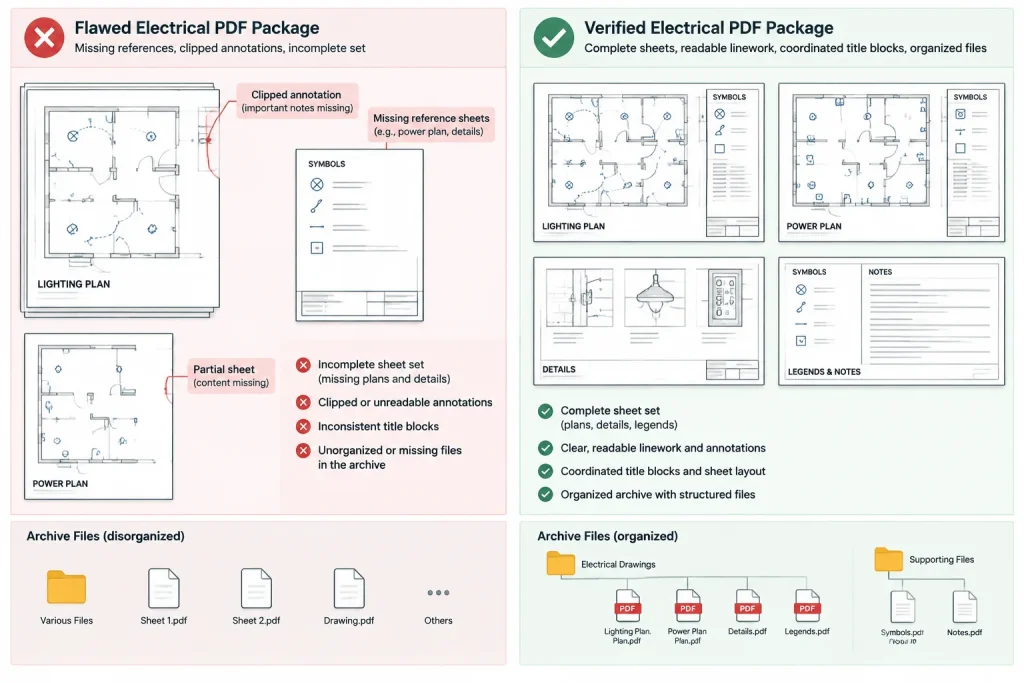
Review graphic output
- Check lineweight hierarchy and background screening.
- Confirm that text remains readable and is not covered by masks or hatches.
- Look for missing symbols, blank viewports, and clipped sheet edges.
- Inspect raster images and shaded content for acceptable clarity.
- Confirm that monochrome or color-dependent information remains understandable in the intended output.
Review package behavior
- Confirm that sheets appear in the intended order.
- Check PDF sheet names or bookmarks if they are part of the required workflow.
- Test representative text searches rather than assuming all annotations are searchable.
- Open the package independently from the publishing session.
- Confirm that the file names identify the project and issue without relying on a user’s local folder structure.
If individual-sheet PDFs and a combined set are both required, verify both outputs. A combined package can be complete while one of the separate files is outdated, or vice versa.
Run a final package-level review
Before release, compare the final output against the issue sheet matrix. Count the sheets, confirm the first and last expected sheets, and investigate any duplicate or missing numbers. Review the drawing index against the actual files rather than against the CAD sheet list alone.
Remove temporary plots, superseded files, internal markups, and unrelated exports from the delivery folder. If native CAD files are included, check that the package contains only the requested support files and does not expose unnecessary working material.
Archive enough information to reproduce the issue
A useful archive should make it possible to determine what was sent and what produced it. Retain the final transmitted output, the issue sheet matrix or equivalent record, and the applicable source-file snapshot according to project policy. Preserve transmittal information and approved exceptions when those records are part of the team’s workflow.
Avoid reopening an archived issue and silently correcting it. If a released package needs correction, handle the change through the project’s revision and communication process so that recipients can distinguish the original issue from the replacement.
A practical release sequence
- Define the purpose, scope, and required deliverables.
- Establish the source-file freeze point.
- Create or update the issue sheet matrix.
- Check CAD references, viewports, layers, annotations, and title blocks.
- Reconcile plans, diagrams, schedules, and cross-references.
- Publish the required outputs.
- Inspect the actual PDFs and native-file package.
- Compare the final package with the sheet matrix and drawing index.
- Remove temporary or superseded material.
- Transmit and archive the verified issue snapshot.
The strongest electrical drawing issue workflow is repeatable and visible. By treating publishing as a controlled documentation process rather than a last-minute plot task, CAD teams can reduce missing sheets, mixed revisions, unresolved references, and cross-drawing conflicts.
Turn the workflow into a controlled release gate
A checklist is most effective when every item has a responsible reviewer, a visible status, and a record of any accepted exception. Simply circulating an unchecked list does not establish that the package was reviewed. The issue sheet matrix, marked review files, publishing logs, or equivalent project records should show what was examined and what remains unresolved.
Assign checks by responsibility
Package assembly, CAD review, drawing coordination, and authorization to release may belong to different people. Identify those roles before publishing so that a drafting check is not mistaken for design approval and a successful export is not mistaken for release authorization.
Classify findings consistently
Teams benefit from distinguishing between conditions that prevent release, corrections that can be completed before publishing, and documented exceptions accepted by the authorized reviewer. The exact terminology can follow the project procedure, but ambiguous comments such as check later should not remain in a package that is ready for transmission.
Preserve review evidence
Retain enough information to connect the final files with the reviewed files. Useful evidence can include the completed sheet matrix, resolved markup record, final output folder, transmittal data, and the source-file snapshot used for publishing. This supports later questions without implying that the archive replaces formal project records.
Common warning signs before release
- A sheet appears in the drawing index but not in the delivery folder.
- The combined PDF and individual-sheet files were produced from different source states.
- Title-block data agrees visually, but file names or transmittal information identify another issue.
- A reference displays correctly only on the publishing workstation.
- Cross-references point to sheets or details excluded from the current package.
- Review comments were removed from view without a recorded resolution.
- The archive cannot identify which CAD files produced the transmitted output.
Any of these conditions should prompt investigation before release. The objective is not merely a clean-looking plot; it is a coherent and reproducible issue package whose contents match the approved publishing scope.
Frequently asked questions
What is the difference between a plot set and an electrical drawing issue package?
A plot set is the visible collection of published sheets. An issue package also includes the release context, such as its purpose, revision state, required file formats, sheet scope, and supporting records. Depending on project requirements, it may contain separate PDFs, native CAD files, reference files, or transmittal information.
Should CAD files or PDFs be checked first?
Both require review for different reasons. CAD review helps identify reference, layer, viewport, attribute, and resource problems. Output review confirms what recipients will actually see. A correct-looking CAD layout does not guarantee a correct published file.
Who should approve an electrical drawing package for release?
The project’s established responsibility and authorization process should determine approval. CAD staff may verify document assembly and graphic output, while engineering, project management, or other authorized personnel may hold separate review responsibilities. Drafting quality control should not be represented as engineering approval.
Why is a source-file freeze point useful?
It identifies the file state used to create the issue. Without a controlled freeze point, ongoing edits can cause sheets in the same package to reflect different revisions or make the released set difficult to reproduce.
What should happen when a problem is found after transmission?
Do not silently replace the archived package. Record the problem and follow the project’s approved revision, notification, and reissue process so recipients can distinguish the corrected release from the original issue.
Can automated publishing replace visual review?
No. Automation can improve consistency and identify certain missing files or publishing errors, but it may not detect weak lineweight hierarchy, obscured notes, conflicting drawing information, or misleading sheet content. The actual deliverables still require an appropriate review.










Leave a Reply
You must be logged in to post a comment.