
Coordinating electrical symbols across multiple drawing types requires more than copying the same geometry from sheet to sheet. Each representation must communicate the information appropriate to its view while remaining traceable to the same device or equipment identity.
This guide explains how to organize related plan, elevation, section, and diagram blocks as a practical family. It focuses on drafting consistency, shared attributes, purposeful insertion points, library naming, and checks that help prevent symbolic graphics from being confused with verified physical layouts.
An electrical device may appear several times in the same drawing set, but it should not necessarily look the same in every view. A panelboard shown as a wall-mounted rectangle on a floor plan may need a front-facing outline on an elevation, a simplified enclosure in a section, and a schematic symbol on a single-line diagram.
Treating these graphics as an electrical CAD block family helps drafters keep related representations organized without forcing one block to perform every documentation task. The goal is not to make all views visually identical. It is to preserve the identity and design intent of the device while using the graphic form appropriate to each drawing.
What Is an Electrical CAD Block Family?
A block family is a coordinated group of CAD definitions representing the same device, equipment category, or functional concept in different drawing contexts. Depending on the project, a family may include:
- A plan-view symbol or equipment footprint
- A front or side elevation
- A simplified section representation
- A single-line or riser-diagram symbol
- A schematic or wiring-diagram symbol
- A detail component used in mounting or connection drawings
- A legend sample showing the project’s graphic convention
These blocks are related by identity, not necessarily by geometry. A plan footprint communicates location and occupied area. A diagram symbol communicates electrical relationships. An elevation communicates mounting arrangement and coordination with walls, doors, ceilings, or adjacent equipment.
Why One Universal Block Usually Fails
It may seem efficient to create one detailed block and reuse it everywhere. In practice, a universal block often produces drawings that are either too detailed or too vague.
For example, a realistic equipment outline may work on an enlarged plan but become unreadable on an overall floor plan. The same outline may be misleading on a single-line diagram, where enclosure shape matters less than the connection between source, protective device, feeder, and load.
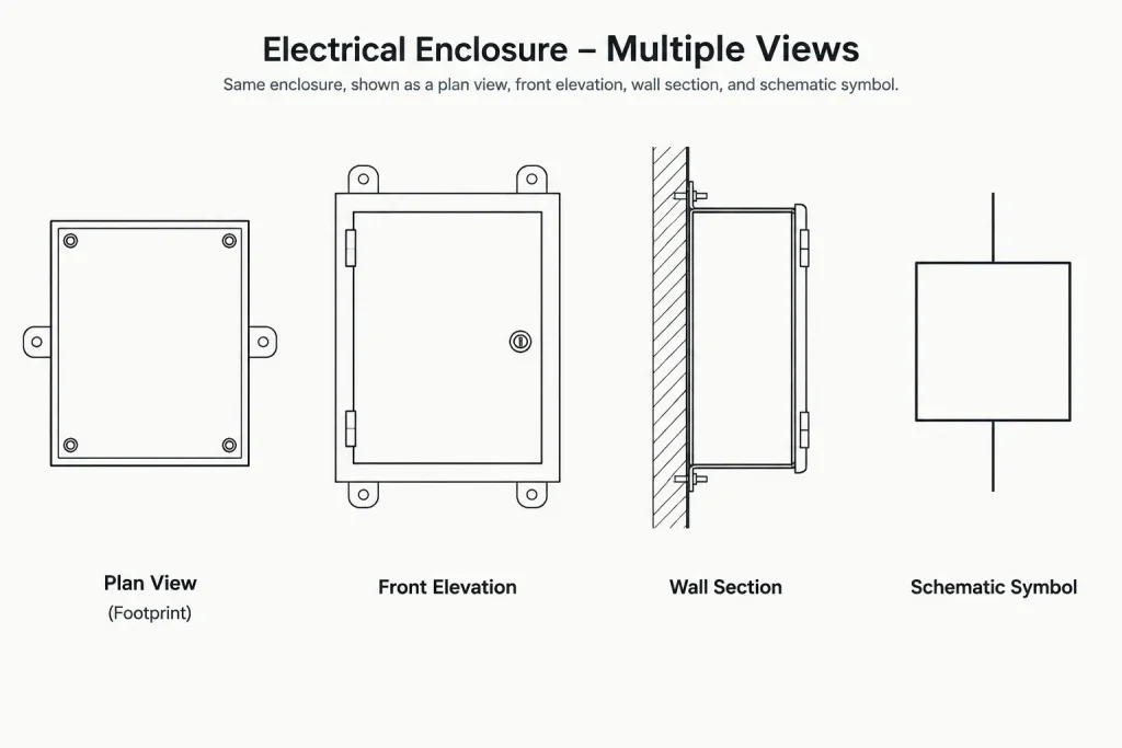
Using separate representations also avoids confusing physical scale with symbolic scale. Plan footprints are commonly intended to coordinate with the building background, while schematic graphics are arranged for clarity and may not represent physical dimensions or relative locations.
| Representation | Primary purpose | Typical information | Common drafting risk |
|---|---|---|---|
| Plan | Locate and coordinate the device | Footprint, orientation, tag, connection point | Using a generic symbol where actual footprint coordination is needed |
| Elevation | Show vertical placement and access relationship | Enclosure outline, mounting surface, nearby obstructions, tag | Implying unverified dimensions or mounting details |
| Section | Explain depth and construction interfaces | Wall, floor, support, raceway approach, equipment depth zone | Adding construction assumptions not supported by project information |
| Single-line or riser | Show system hierarchy and electrical connections | Sources, feeders, buses, devices, loads, references | Making the symbol resemble a footprint instead of a functional diagram |
| Schematic or wiring diagram | Describe functional or point-to-point relationships | Contacts, coils, terminals, conductors, control relationships | Assuming a schematic represents physical terminal arrangement |
Start with a Shared Equipment Identity
The strongest link between family members is a consistent identifier. A panel shown on a plan, elevation, and single-line diagram should carry the same project tag where that tag is intended to identify the same asset. The graphics can change while the identifier remains stable.
Useful shared data may include an equipment tag, type designation, drawing reference, system classification, or schedule key. Only include fields that the project team can maintain reliably. Attributes that are routinely blank, duplicated, or manually overridden can create false confidence.
When blocks contain attributes, use matching attribute names across related family members where practical. This can make review and data extraction easier. However, not every representation needs every field. A schematic symbol may need a circuit or connection reference, while a plan block may need mounting or location information.
Develop Each View for Its Actual Job
Plan-view blocks
Decide whether the plan graphic is a symbolic marker, a coordination footprint, or a combination of both. Small devices such as switches and receptacles are often represented symbolically because their visible CAD graphics need to remain legible. Larger equipment may require a footprint based on verified project or manufacturer information.
Keep insertion points intentional. A wall device may benefit from a point located at its mounting surface, while freestanding equipment may use a meaningful corner, centerline, or connection location. The insertion point should support consistent placement and rotation rather than simply reflecting where the original geometry happened to be drawn.
Elevation and section blocks
Elevation blocks should communicate the face and mounting relationship that the viewer needs to coordinate. Avoid filling a general library block with invented knockouts, handles, vents, or internal arrangements. Such details vary by equipment and can imply a level of product selection that has not occurred.
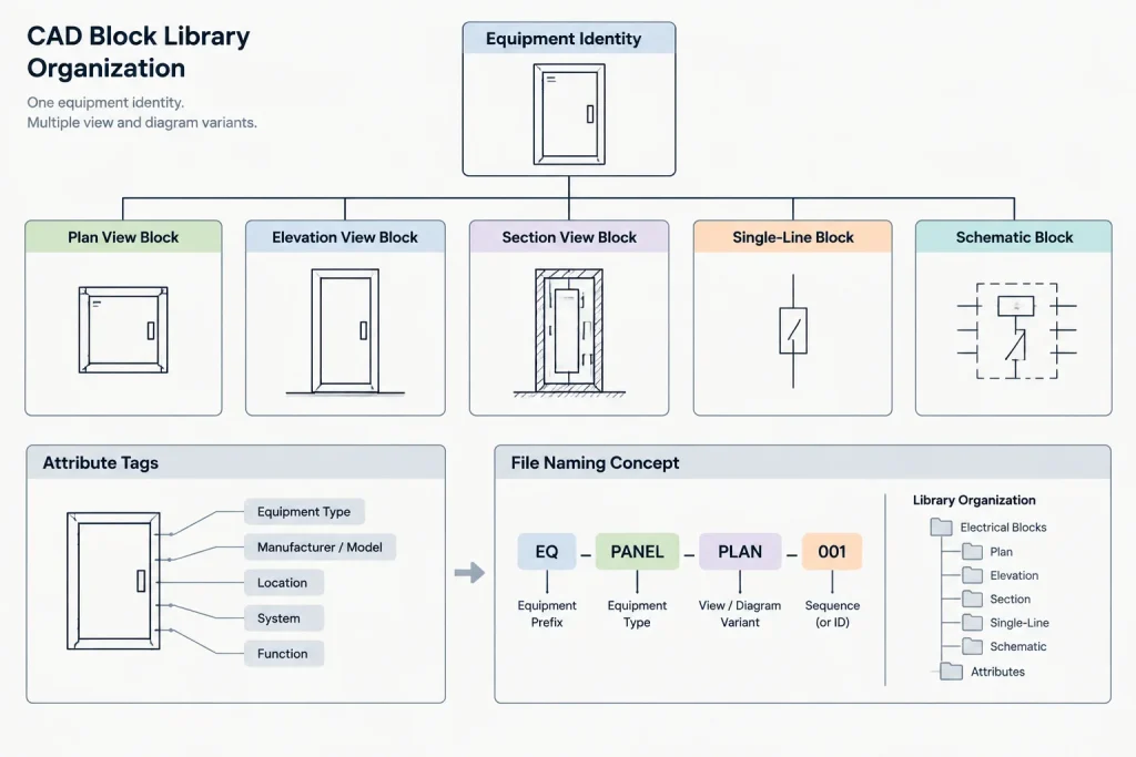
Section blocks should be equally disciplined. Show only the construction interface required for the detail. If equipment depth, support, or raceway entry depends on a selected product, use a clearly generic representation or replace it with verified project information.
Diagram symbols
Diagram blocks should prioritize connectivity, hierarchy, and readable annotation. Their connection points need to align with the drawing’s diagram structure. Consistent attachment points reduce crooked conductors, short line fragments, and unnecessary editing when a diagram is rearranged.
Do not assume that a terminal shown schematically occupies the same physical position on the actual device. When physical termination matters, coordinate the schematic with terminal drawings, wiring diagrams, or verified equipment documentation.
Use a Predictable Naming Structure
A shared root name can make family members easier to find. Add a suffix that identifies the representation rather than relying on visual inspection. A library might distinguish plan, elevation, section, single-line, schematic, and detail variants using its own documented abbreviations.
The exact convention is less important than consistency. Avoid names such as “new,” “final,” or “updated,” because they do not explain the block’s purpose and quickly lose meaning. Revision status belongs in controlled library records or metadata, not in an ambiguous block name.
A useful family record can document:
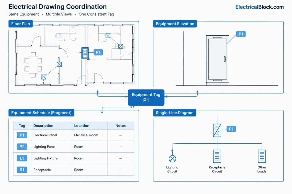
- The common equipment or device category
- Available drawing representations
- Intended insertion and rotation behavior
- Attribute definitions shared across variants
- Whether geometry is symbolic, generic, or based on verified data
- The library revision owner or review status
Coordinate Graphics Without Making Them Identical
Family resemblance can come from tagging, annotation placement, line hierarchy, and terminology rather than repeated geometry. Use the same equipment identifier and description where applicable. Keep text styles, attribute justification, and layer behavior aligned with the project CAD standard.
Color and layer alone should not be the only ways to distinguish representations. Those properties may change when files are referenced, exported, or plotted. The symbol should remain understandable through its form, label, and drawing context.
If visibility states or configurable blocks are part of the office workflow, they may help manage closely related variants. They should not conceal major differences in purpose. A symbolic plan marker and a dimensionally coordinated footprint may be safer as separate definitions because substituting one for the other could affect layout decisions.
A Practical Block-Family Workflow
- Define the device category. Determine whether the family represents a generic type, a scheduled type, or a specific selected item.
- List required representations. Create only the views needed by the drawing set and library users.
- Identify shared data. Establish the tag and other attributes that connect the family members.
- Draft each representation independently. Optimize geometry for the purpose and scale of its drawing context.
- Set meaningful insertion points. Test placement against walls, grids, connection lines, and diagram buses.
- Apply naming and layer rules. Make the family searchable and predictable.
- Test plotting and references. Confirm that symbols remain readable in viewports and when backgrounds are screened.
- Review substitutions. Check that users cannot easily confuse a generic symbol with a verified footprint or product-specific detail.
Quality-Control Checks Across the Drawing Set
Block-family review should extend beyond the library file. Compare the actual sheets where related representations appear.
- Does the equipment tag match on plans, elevations, schedules, and diagrams?
- Does the plan orientation agree with the elevation or section callout?
- Are connection points shown on the correct side when that information is verified?
- Is symbolic geometry clearly distinguishable from a physical footprint?
- Are generic blocks being mistaken for manufacturer-specific outlines?
- Do demolition, existing, future, or new-work graphics use the project’s status conventions?
- Can each representation be traced to the appropriate schedule, detail, or diagram?
- Are unused attributes, hidden fragments, and stray nested blocks removed?
Library Blocks Are Starting Points, Not Project Verification
An electrical CAD block family improves consistency, but it does not validate equipment selection or installation requirements. Before a footprint, elevation, connection location, or mounting arrangement is used for project coordination, it should be checked against current project criteria and verified equipment information.
The most useful block library makes that distinction visible. Generic symbols support early drafting and system communication. Verified project blocks support detailed coordination. Keeping those roles separate helps prevent a convenient graphic from being treated as design evidence it was never intended to provide.
Applying the Family Concept in a CAD Library
Before adding related blocks to a shared library, document what each representation is intended to communicate. A short purpose statement can help users choose between a symbolic marker, a generic equipment outline, a coordination footprint, and a functional diagram symbol.
Separate identity from representation
The equipment tag or type reference establishes the relationship between family members. Geometry establishes how that equipment is communicated in a particular drawing context. Keeping these roles separate allows a plan block and a diagram block to look different without appearing to describe different assets.
Record the status of the geometry
Library metadata should indicate whether a block is symbolic, generic, project-verified, or based on selected equipment information. This distinction is especially important for footprints, connection locations, mounting relationships, and access-dependent outlines. A descriptive status is more useful than a vague filename suggesting that a block is merely current or final.
Test family members together
Reviewing blocks only in isolated library files can hide coordination problems. Place related representations in representative plan, elevation, section, and diagram conditions, then compare identifiers, orientation, annotation behavior, connection points, and plotted clarity.
Questions for a Block-Family Review
- Can a user identify the intended drawing context from the block name and library description?
- Do shared attributes use consistent names and meanings?
- Is the insertion point appropriate for placement, rotation, and connection?
- Does the graphic remain understandable without relying only on color?
- Is generic geometry clearly distinguished from verified project geometry?
- Can reviewers trace each representation to the same equipment tag, schedule entry, or drawing reference?
- Will replacing one family member affect physical coordination or only graphic presentation?
These checks support consistent documentation, but they do not replace review against current project criteria, selected equipment data, or the governing CAD standard.
Frequently Asked Questions
Should every electrical device have plan, elevation, section, and diagram blocks?
No. A family should contain only the representations needed for the drawing set and documentation workflow. Creating unused variants adds maintenance work and can make the library harder to search.
Can one configurable block contain every representation?
It can be useful when the variants share a clear purpose and users can select them reliably. Separate definitions are often safer when one graphic is symbolic and another is intended for physical coordination, because an incorrect substitution could misrepresent design intent.
What should remain consistent across family members?
The shared equipment identity, terminology, applicable attributes, annotation conventions, and library classification should remain coordinated. The geometry may change substantially to suit each drawing type.
Is a diagram symbol expected to match the physical equipment outline?
No. A diagram symbol primarily communicates function, hierarchy, or connectivity. It should not be interpreted as a physical footprint, terminal layout, or installation arrangement unless verified documentation explicitly establishes that relationship.
How should generic and project-specific blocks be distinguished?
Use clear library names, descriptions, metadata, or approved project status conventions. Users should be able to tell whether geometry is conceptual, generic, or verified without relying on appearance alone.
Why are insertion points important across a block family?
Insertion points influence placement, rotation, alignment, and connection behavior. A meaningful point helps a plan block align with a wall or equipment location and helps a diagram symbol connect cleanly to conductors or buses.


Leave a Reply
You must be logged in to post a comment.