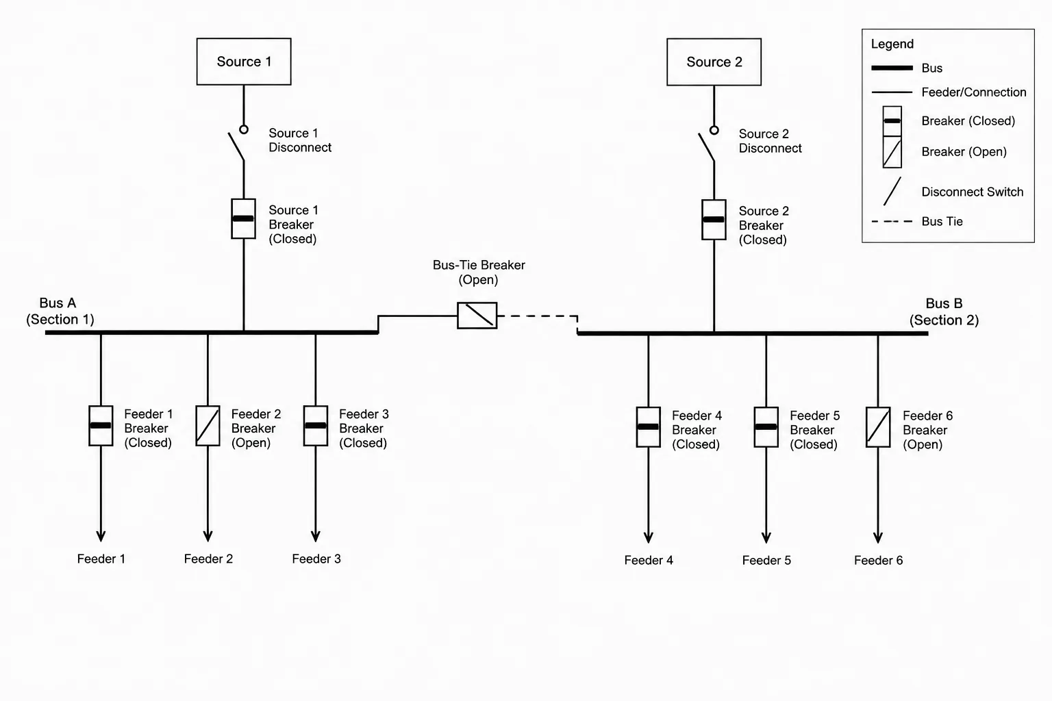
Open and closed device status can change how readers interpret the source path, bus arrangement, and intended configuration of an electrical single-line diagram. Clear drafting requires more than selecting a recognizable breaker or switch symbol; the drawing must also define what the depicted position means.
This reference focuses on practical CAD documentation choices for breakers, disconnects, bus ties, transfer devices, and related distribution equipment. It explains how to combine symbol geometry, status labels, legends, block attributes, and drawing coordination without turning a design diagram into an operating procedure.
A single-line diagram shows how electrical sources, distribution equipment, feeders, and major loads relate to one another. Device symbols alone, however, may not explain the intended configuration. A breaker, disconnect, bus tie, or transfer device may be drawn in an open or closed position, but readers still need to know what that position represents.
Is it the normal operating state, an existing field condition, a proposed configuration, or merely the symbol’s default appearance? Clear status documentation answers that question without turning the drawing into an operating procedure.
This guide explains how to represent open and closed device status consistently in CAD, coordinate that information across related drawings, and avoid common notation problems.
Why device status matters on a single-line diagram
The same distribution arrangement can function differently depending on the position of a small number of devices. A normally open bus tie may keep two sections separated. A closed tie may connect them under a documented alternate condition. An open main device can indicate an unused source, while a closed main may represent the normal supply path.
If status is unclear, readers may misinterpret:
- Which source normally supplies a bus or load
- Whether two sources operate in parallel or remain isolated
- Which section is energized in the documented normal configuration
- Whether a feeder is active, spare, future, or disconnected
- How a transfer arrangement is intended to appear in its normal state
- Whether the diagram represents design intent or a surveyed condition
The drawing should communicate configuration intent, but it should not instruct personnel to operate equipment. Switching procedures, safety controls, and field authorization belong in controlled operational documents prepared by qualified parties.
Define what “normal” means for the drawing
The word normal can be ambiguous. On a power single-line diagram, it often refers to the expected operating configuration. In a control schematic, normally open and normally closed contacts may instead be shown in a defined de-energized or unactuated condition. These are related concepts, but they are not interchangeable.
A single-line diagram should include a note or legend statement that defines the basis of its device positions. For example, the drawing may state that switching devices are shown in the normal operating configuration unless specifically noted otherwise. The exact wording should match the project’s documentation practices and be reviewed by the responsible design team.
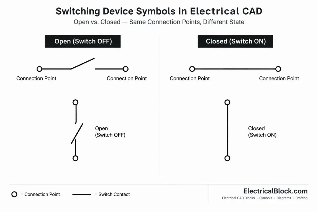
Avoid relying on an unexplained “NO” or “NC” label. Depending on context, those abbreviations can refer to a power device’s expected position, a relay contact state, or the state associated with a particular equipment condition.
Choose a consistent graphic method
There are several reasonable ways to document device status. The best choice is the method already established by the project legend, client standard, or drawing convention. Consistency is more important than adding multiple redundant indicators.
Symbol position
A switch or breaker symbol can be drawn with its moving element visibly separated from the fixed contact to indicate open status. A connected graphic can indicate closed status. This method is fast to read when the diagram is plotted at its intended size.
Symbol position should not be the only cue when the graphic difference becomes difficult to see after reduction, scanning, or monochrome plotting.
Text labels
A short status label can be placed beside the device, such as “NORMALLY OPEN” or “NORMALLY CLOSED.” Text is especially helpful for bus ties, source isolating devices, and other components whose status materially affects the distribution arrangement.
Keep the label close enough to establish ownership without crowding the device tag, rating information, feeder callout, or cross-reference.
Line type, fill, or screening
Some drawing systems use alternate linework or screening to distinguish inactive paths. This can support diagram comprehension, but it should not replace explicit status notation. Line types may be lost during plotting, and screening can be confused with existing-work, demolition, or future-work graphics.
If line appearance carries meaning, explain it in the legend and verify that it remains recognizable in the final PDF and printed set.
Devices that commonly need status notation
| Device or arrangement | Documentation question | Useful drawing treatment |
|---|---|---|
| Main breaker or disconnect | Is this source connected in the documented normal configuration? | Show symbol position and add a status note when the condition is not obvious. |
| Bus tie | Are adjacent bus sections normally connected or separated? | Use an explicit status label because the tie position can change the system topology. |
| Alternate source device | Is the alternate source available, connected, or isolated? | Identify the source and distinguish availability from actual connection. |
| Transfer equipment | Which source is designated normal, and what state is represented? | Label source roles and coordinate the one-line with the associated control documentation. |
| Spare or future feeder device | Does the device exist, and is a feeder connected? | Combine status with a clear spare, space, or future designation as applicable. |
| Drawout or removable device | Does the diagram describe contact position, connected position, or equipment availability? | Avoid compressing several different conditions into a single open or closed label. |
Separate electrical state from project status
Open and closed describe an electrical switching condition. Existing, new, relocated, spare, future, and removed describe project or installation status. These categories should not be blended.
For example, a future breaker position is not necessarily an open breaker. It may be an unoccupied provision with no device installed. Similarly, an existing breaker shown open may still be active equipment intended to remain.
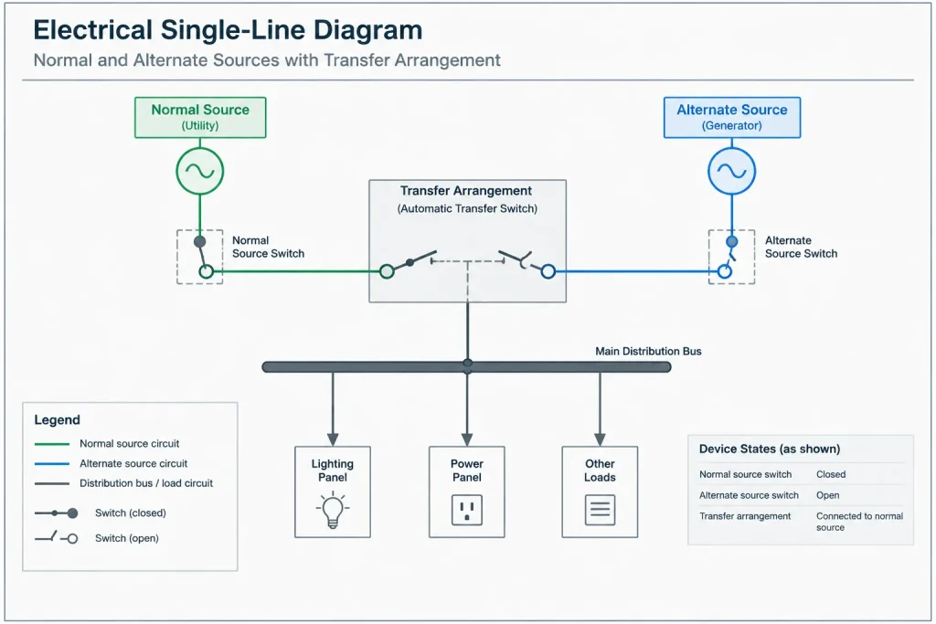
Use separate attributes, notes, layers, or labels for:
- Device identification
- Open or closed configuration
- Existing or proposed scope
- Spare, space, or future designation
- Source and destination references
This separation also makes CAD data easier to review and extract.
Use status tables for multiple configurations
A single diagram can become confusing when it attempts to display normal, emergency, maintenance, and alternate configurations simultaneously. If several valid configurations must be documented, consider pairing the diagram with a device-status table.
The table can list each relevant switching device in rows and each defined configuration in columns. Individual cells then identify the documented state. Configuration names should be descriptive and project-specific rather than generic labels that readers could interpret differently.
A status table should remain an explanatory design document, not a switching sequence. Avoid adding step-by-step operating instructions unless they belong to a separately controlled procedure developed and approved for that purpose.
Build status into CAD blocks carefully
CAD blocks can improve consistency, but a device block should not hide important status information. A practical block may include:
- A stable device tag insertion point
- Separate open and closed visibility options or symbol variants
- An optional status attribute
- Connection points that stay aligned when the symbol changes
- Consistent text placement for identification and cross-references
Do not assume that changing an attribute automatically changes the symbol geometry unless the block has been intentionally built and tested to do so. A label reading “OPEN” beside a graphically closed symbol creates a direct contradiction.
Where block variants are used, name them according to the library’s drafting convention rather than embedding project assumptions into a generic symbol. Project-specific status should remain editable and reviewable.

Coordinate status across related documents
Device status shown on the single-line diagram may also affect risers, control diagrams, equipment schedules, sequence narratives, and vendor drawings. These documents do not need identical graphics, but they should describe a compatible configuration.
During coordination, verify that:
- Device tags match across diagrams and schedules.
- Normal and alternate sources are named consistently.
- Bus-tie status agrees with the depicted source paths.
- Transfer-device source designations match associated control documents.
- Future or spare devices are not represented elsewhere as active feeders.
- Revision notes identify configuration changes that affect system interpretation.
When vendor information is incorporated, preserve a distinction between the design diagram and manufacturer-specific internal arrangements. Simplifying a vendor drawing for the project one-line should not change the documented functional relationship.
Review the diagram as a connected system
Status review should go beyond checking individual symbols. Trace each depicted source through the diagram and ask whether the resulting paths make sense under the stated configuration.
A focused CAD quality-control pass can include these steps:
- Read the legend note defining device positions.
- Locate every main, tie, transfer, and alternate-source device.
- Compare each symbol position with its adjacent text label.
- Trace normal source paths to downstream buses and major loads.
- Look for unintended source connections or isolated sections.
- Compare tags and status descriptions with schedules and related diagrams.
- Plot or export the sheet and confirm that open gaps, labels, and line types remain legible.
Any real project configuration must be verified against current design information, equipment documentation, and qualified engineering review. A generic CAD symbol or example should never be treated as confirmation of an actual equipment state.
Common drafting errors
- Undefined symbol positions: Devices are drawn open or closed, but no note explains the basis.
- Conflicting cues: The symbol appears closed while the status attribute says open.
- Overloaded abbreviations: “NO” and “NC” are used without identifying whether they apply to power devices or control contacts.
- Project status substituted for device state: A future or spare designation is treated as equivalent to open.
- Color-only meaning: Source paths or inactive devices can no longer be distinguished on monochrome output.
- Uncoordinated tie status: The displayed bus arrangement conflicts with notes or other diagrams.
- Operational instructions embedded in design drawings: A diagram intended to describe topology becomes an uncontrolled switching procedure.
A clear documentation objective
A well-drafted single-line diagram lets a reader identify the intended configuration without guessing from symbol geometry alone. Define the basis of device positions, reserve explicit labels for significant conditions, separate electrical state from project status, and coordinate every important device with related documentation.
The objective is not to show every possible operating condition on one sheet. It is to present a clear, internally consistent representation of the configuration the drawing is intended to document.
Practical interpretation guide
When reviewing a device on a single-line diagram, treat its graphic position, written status, equipment identity, and project status as separate pieces of information. These elements should support one another rather than force the reader to infer intent.
- Graphic position communicates whether the symbol is depicted open or closed.
- Status wording explains the intended meaning of that depicted position.
- Device identification connects the symbol to schedules, notes, and related drawings.
- Project status identifies whether equipment is existing, proposed, spare, future, relocated, or removed.
- Configuration context establishes whether the sheet represents normal, alternate, maintenance, surveyed, or another defined condition.
A reliable drawing does not make one category stand in for another. An open symbol does not automatically mean spare, and a future designation does not confirm that a switching device is installed.
Final CAD handoff check
Before issuing or exchanging the drawing, review it in the same form that recipients will use. Confirm that open contact gaps remain visible, status text is associated with the correct device, and monochrome output preserves every distinction needed to understand the configuration.
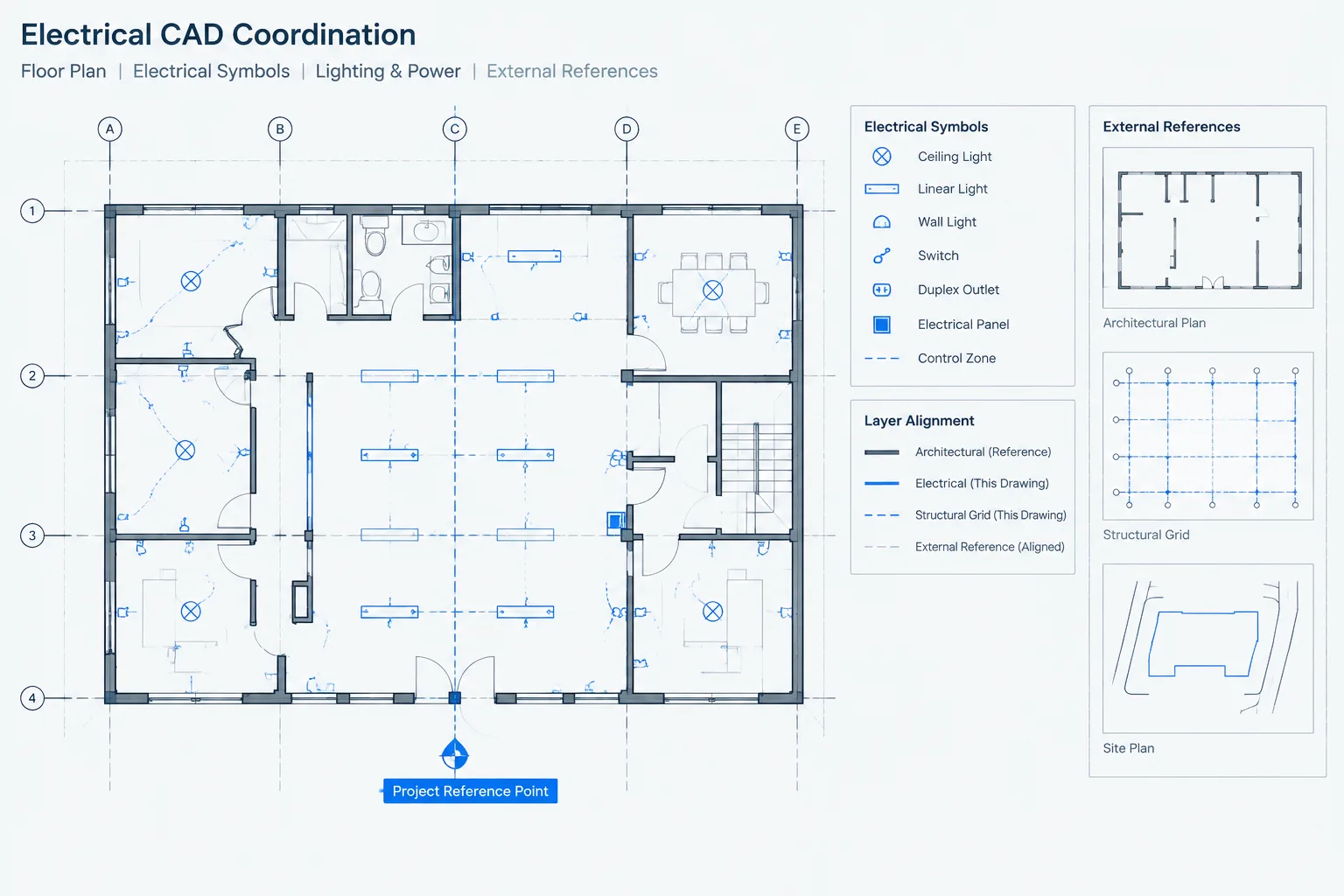
Also check that block attributes and visible geometry agree after editing, copying, mirroring, or changing visibility states. If the file will be referenced into another drawing, verify that layer mapping and plotting conventions do not hide status information.
The completed single-line diagram should communicate a defined design or documentation condition. Actual equipment state, field operation, and switching authorization require separate verification by qualified parties using controlled project and operational information.
Frequently asked questions
Should a single-line diagram show switching devices open or closed?
It should show the position associated with the configuration being documented. A legend note or nearby annotation should define whether that configuration represents normal operation, an alternate arrangement, a surveyed condition, or another stated basis.
Is symbol position enough to document device status?
Not always. Small contact gaps can disappear when a sheet is reduced, scanned, exported, or printed. Significant devices may need an explicit status label in addition to clear symbol geometry.
Do normally open and normally closed mean the same thing on every drawing?
No. On a power single-line diagram, the terms may describe an expected distribution configuration. On a control schematic, they may refer to contact condition under a defined unactuated or de-energized basis. The drawing context and legend must make the intended meaning clear.
Is a future or spare device the same as an open device?
No. Open and closed describe switching state. Future, spare, and space describe installation or project status. A future provision may not contain an installed device, while an existing device can be intentionally shown open.
Can color or screening identify inactive paths?
Color and screening can support readability, but they should not carry essential meaning by themselves. The same distinction should remain understandable in monochrome output and should be explained in the drawing legend.
How should multiple valid configurations be documented?
Keep the primary diagram focused on a clearly defined configuration. When other configurations must be compared, use coordinated notes, separate diagrams, or a device-status table. Do not present the comparison as an uncontrolled switching sequence.
What should be checked in a dynamic CAD block?
Confirm that each visibility state displays the intended geometry, keeps connection points aligned, and agrees with any status attribute. Changing text alone should never leave an open label beside a graphically closed device, or the reverse.








Leave a Reply
You must be logged in to post a comment.