
A capacitor schematic symbol DWG block gives drafters a reusable way to represent capacitor components in electrical and electronic drawings. Instead of redrawing each symbol, a CAD user can place the appropriate graphic into a circuit diagram, schematic, or related design document and keep the drawing language consistent.
This resource is useful when developing symbol libraries, preparing electrical legends, or coordinating schematic content with broader CAD documentation. It is intended as a drafting reference, not as a substitute for checking the symbol convention, project standards, or engineering requirements that apply to a particular drawing set.
Discover a comprehensive DWG file featuring detailed schematic symbols for capacitors, perfect for electrical and electronic circuit design. This CAD block offers clear, standardized representations of various capacitor types, streamlining your drafting process. Ideal for engineers, architects, and students, these schematic symbols ensure accuracy and professionalism in your projects. The file is fully compatible with AutoCAD and other major CAD software, making it easy to incorporate into your existing designs. Enhance your schematic diagrams and electrical plans with this essential resource for any technical drawing involving capacitors.
Please log in or register to download this file.
What the capacitor DWG block represents
In a schematic, a capacitor symbol communicates the presence and graphical identity of a capacitor without depicting its physical package or installation method. The surrounding wires, connection points, labels, and notes provide the context needed to understand how the component relates to the rest of the circuit.
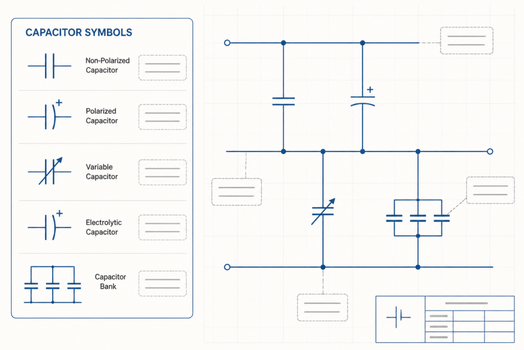
The source file includes detailed schematic representations for various capacitor types. Before placing a symbol, compare the available forms with the convention used by the project, company, or drawing legend. Consistent symbol selection helps readers distinguish component intent and reduces ambiguity during design review.
How to use the block in an electrical CAD workflow
- Review the symbol first: Confirm that the selected representation matches the intended capacitor category and the drawing convention being used.
- Place it with clear connections: Keep connection points aligned with the schematic wiring so the component relationship is easy to follow.
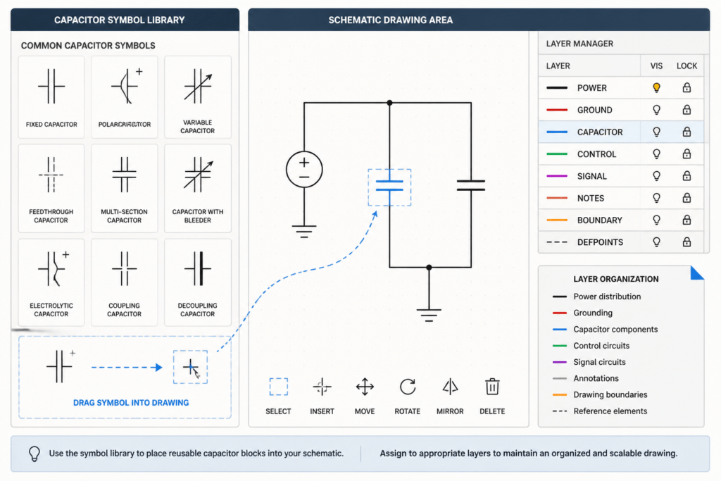
- Apply project drafting standards: Use the appropriate layer, line properties, text style, and reference designation required by the drawing set.
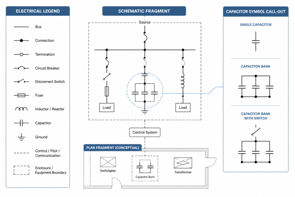
- Coordinate surrounding documentation: Check the electrical legend, circuit notes, single-line diagrams, and panel or equipment documentation for consistent terminology.
- Verify before issue: Treat the block as a graphic drafting resource. Engineering review is still needed to confirm the component information and circuit design.
Related electrical drawing topics
A capacitor symbol is most useful when it fits into a well-organized CAD system. Related reference material may include electrical symbol legends, CAD layer practices, single-line diagram conventions, schematic annotation, and drawing-reading guidance. Reviewing these topics together can help users understand not only what a symbol looks like, but also how it functions within a complete set of electrical documents.
Compatibility and file use
The source describes the file as compatible with AutoCAD and other major CAD software. Compatibility should still be checked in the user’s own CAD environment, especially when blocks are transferred between templates, drawing standards, or software versions. Inspect the inserted geometry, attributes, layer behavior, and connection points before relying on the block in a project drawing.
Frequently asked questions
What is a capacitor schematic symbol DWG block?
It is a reusable CAD drawing resource containing graphical representations of capacitor symbols for use in electrical and electronic schematics.
Who can use this capacitor symbol resource?
Electrical designers, engineers, architects working with coordinated drawing sets, CAD drafters, and students can use it as a drafting and study reference.
Can the block be used in AutoCAD drawings?
Yes. The source identifies the file as compatible with AutoCAD and other major CAD software. Users should inspect the imported block in their own template before project use.
Does the symbol block verify a circuit design?
No. A CAD symbol communicates graphic information only. Component selection, circuit relationships, design intent, and project compliance require appropriate engineering review.
Where should capacitor symbols appear in electrical documentation?
They may appear in schematic diagrams and related electrical drawing views where component relationships need to be communicated. The exact placement and annotation should follow the applicable project drafting convention.




Leave a Reply
You must be logged in to post a comment.