
Lighting control drawings in CAD must communicate several related but distinct ideas: where devices are located, which luminaires operate together, how control commands move through the system, and where operating intent is documented. Clear separation of these relationships helps prevent control zones from being mistaken for branch circuits or communication paths.
This reference explains how plans, tags, diagrams, matrices, legends, and CAD layers can work together as a coordinated documentation system. It focuses on drawing organization and review rather than product-specific wiring or field installation.
Lighting control documentation connects several kinds of information that are easy to confuse on a crowded electrical plan. A fixture may belong to a branch circuit, respond to more than one control device, participate in a programmed scene, and operate differently under normal and backup power conditions. Trying to communicate all of this with a single switch line often produces an unreadable drawing.
Effective lighting control drawings in CAD separate physical location, control intent, circuit information, and system logic while maintaining clear references among them. The goal is not to reproduce every internal function of a control product. It is to give designers, reviewers, installers, programmers, and facility personnel a coordinated description of what is controlled, where the associated devices are located, and which project document defines each relationship.
Start by Separating the Main Information Types
A lighting plan can contain several relationships that look similar graphically but serve different purposes. Establish the meaning of each line, tag, and boundary before drafting.
| Information type | What it communicates | Typical drawing location |
|---|---|---|
| Branch circuit | The electrical supply relationship between fixtures and distribution equipment | Lighting plan, panel schedule, or circuiting plan |
| Control zone | A group of fixtures intended to respond together to a control command | Lighting control plan or zone diagram |
| Device association | Which switches, sensors, stations, or interfaces affect a zone | Plan, keyed notes, matrix, or control diagram |
| System communication | Logical or physical links among controllers, gateways, panels, and interfaces | Control riser or schematic diagram |
| Sequence of operation | How the system is expected to respond to occupancy, schedules, manual commands, or other inputs | Control narrative, matrix, or specification reference |
A control zone is not automatically the same as a branch circuit. Multiple zones may share a circuit, or one coordinated control group may include fixtures supplied from different circuits. The drawing should not imply that circuit grouping and control grouping are interchangeable unless the design specifically establishes that relationship.
Choose a Drawing Structure That Matches Project Complexity
Small projects may communicate lighting and controls on one plan. Larger or denser projects often benefit from separate lighting fixture, lighting circuiting, and lighting control views. Separation reduces graphic congestion, but it also creates a need for disciplined tags and cross-references.
A coordinated drawing set may use some combination of:
- A reflected ceiling or lighting plan showing fixture locations and types
- A circuiting plan showing branch-circuit relationships and home-run information
- A control plan showing stations, sensors, control zones, and local interfaces
- A control riser or schematic showing system-level relationships
- A control matrix matching inputs, zones, actions, and operating modes
- Details for special rooms, repeated arrangements, or unusual interfaces
- Schedules identifying devices, control panels, or fixture control characteristics
Do not split information merely to create more sheets. Use separate views when they make the design easier to read and verify. If two plans use the same architectural underlay, keep their crop boundaries, orientation, room references, and key-plan conventions aligned.
Develop a Clear Zone Identification System
Each control zone should have a stable identifier that remains consistent across plans, diagrams, matrices, and narratives. The identifier does not need to encode every characteristic of the zone. Overly descriptive tags become difficult to maintain when room names or control functions change.

A useful zone workflow is:
-
Identify the fixtures intended to operate together.
-
Assign a unique zone tag according to the project naming convention.
-
Place the tag where it can be associated unambiguously with the fixtures.
-
Reference the same tag from control devices, diagrams, or matrices.
-
Check that every tagged zone appears in the applicable control documentation.
Zone boundaries can be shown with lightweight dashed linework, screened hatching, fixture tags, or keyed notation. The best method depends on plan density. Avoid large opaque fills that hide ceiling geometry, fixture symbols, room names, or other coordination information.
Handling Overlapping Control Functions
A fixture group may be affected by local manual control, occupancy sensing, scheduled commands, daylight response, or an emergency-related interface. Drawing a separate line from every device to every fixture can quickly become impractical.
For simple rooms, control arcs or dashed association lines may be adequate. For spaces with overlapping functions, use zone tags and a matrix rather than a web of lines. The plan can establish device and fixture locations, while the matrix explains which devices affect each zone and what general action is intended.
Tag Control Devices by Function and Identity
Control symbols should distinguish device categories without pretending that every symbol defines a product. A wall station, ceiling sensor, control interface, and centralized panel serve different documentation roles even when their final product selection is deferred.

Where needed, combine a recognizable symbol with an alphanumeric tag. The symbol communicates the general device type; the tag links it to a legend, schedule, note, or diagram. Keep the following separate where the project requires them:
- Device type or functional category
- Unique device identity
- Controlled zone reference
- Network, bus, or system association
- Power source or circuit reference
- Mounting or location note
Do not force all of these fields into one visible tag if it compromises readability. CAD block attributes can store coordinated data while the plan displays only the fields needed for construction-document clarity. Attribute values should still be reviewed because hidden or scheduled data can become outdated even when the visible symbol looks correct.
Use Control Lines Carefully
Control lines are useful when they communicate a direct, simple relationship. They become misleading when readers cannot tell whether a line represents wiring, logical association, communication, or merely design intent.
Define each line type in the legend or drawing notes. A control association line should be graphically distinct from branch-circuit linework and from architectural geometry. If a route is diagrammatic rather than a required physical pathway, state that distinction through the drawing convention or applicable note.
Good linework practices include:
- Keeping association lines lighter than primary fixture and device symbols
- Avoiding lines through text, tags, and dense architectural features
- Using consistent endpoints so readers can identify what a line connects
- Breaking or offsetting lines where crossings would imply false connections
- Replacing excessive lines with zone tags and a matrix
Coordinate Plans with Control Diagrams
The plan shows spatial relationships. A control diagram shows functional organization without depending on room geometry. These views should complement rather than duplicate each other.
A diagram may show control panels, local controllers, stations, sensors, fixtures or fixture groups, interfaces, and connections to other building systems. Keep the diagram at the level of detail appropriate to the project. If vendor shop drawings will define internal terminals or proprietary communication details, the design drawing can identify the required interfaces and functional relationships without inventing unsupported connection information.
Every diagram symbol should either match the plan legend or have its own clearly defined diagram legend. Equipment and zone tags must agree with the plan. If a diagram groups repeated devices for clarity, indicate that it is representative and direct readers to the plans or schedules for quantities and locations.
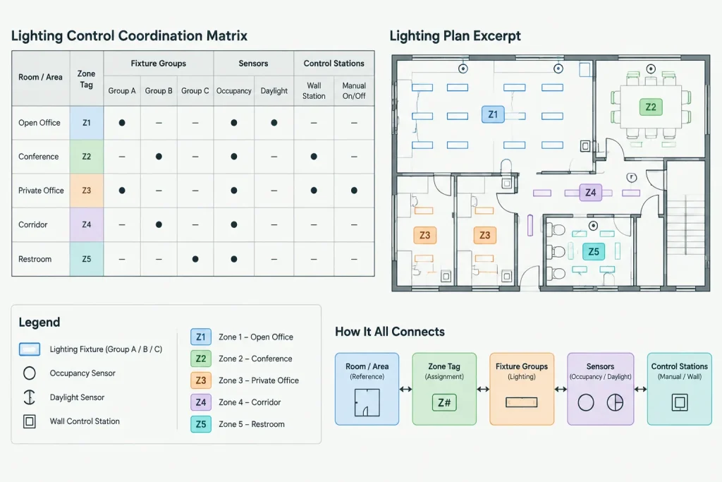
Create a Control Matrix for Complex Relationships
A control matrix is especially useful when multiple input types affect multiple lighting zones. Rows can represent rooms, zones, or operating conditions, while columns can represent devices, commands, or expected responses. The exact format should follow the project’s documentation needs.
A practical matrix may coordinate:
- Room or area reference
- Control zone identifier
- Associated fixture types or groups
- Local control devices
- Sensor or scheduled inputs
- General control response
- Special interface or exception notes
- Related detail, diagram, or sequence reference
Keep narrative programming intent in clear language rather than relying only on abbreviations. Where behavior depends on approved equipment, settings, or owner decisions, identify the item for coordination instead of presenting an unverified function as final.
Build CAD Layers Around Editing and Plotting Needs
Lighting control layers should support both drawing production and review. A project might separate control devices, control association lines, zone boundaries, tags, diagram graphics, and annotation. The exact names are less important than consistent use and reliable plotting.
Layer separation allows drafters to display fixture locations while temporarily hiding circuiting, isolate control annotations for review, and create plan types without duplicating geometry. Avoid placing control information on architectural underlay layers or using color alone to convey meaning. Printed and exported drawings must remain understandable without access to the author’s screen settings.
Run a Coordination Review Before Issue
Lighting control review should test relationships across the entire set, not just the appearance of the control plan. A useful pre-issue check includes:
- Every control-zone tag is unique and legible.
- Every zone referenced by a device, diagram, or matrix exists on the plan.
- Every control device symbol appears in the legend or applicable schedule.
- Fixture types agree with the lighting fixture schedule.
- Branch-circuit information is not mistaken for control-zone information.
- Plan tags match diagram, matrix, and narrative references.
- Repeated rooms and mirrored layouts have been checked for exceptions.
- Normal and backup operating relationships are represented consistently where applicable.
- Interfaces with mechanical, audiovisual, security, fire alarm, or other systems are clearly assigned and referenced.
- Unresolved vendor-dependent information is identified for coordination rather than invented.
- Text, linework, and zone graphics remain readable in the plotted output.
Keep the Documentation Maintainable
Lighting control designs often change as ceiling layouts, room uses, fixture selections, and owner requirements develop. Stable tags, reusable CAD blocks, controlled attributes, and cross-document checks make those changes manageable.
The most useful lighting control drawings do not attempt to place every fact on the floor plan. They assign each fact to the view that communicates it best: location on the plan, grouping through zone tags, functional relationships on diagrams, and operating intent in a matrix or narrative. That division creates a drawing set that is easier to draft, review, revise, and use without confusing electrical supply with lighting control logic.
Trace Control Intent Across the Drawing Set
A useful quality check is to follow the documentation from a room or area through every related drawing. Begin with the fixture and control-device locations, identify the applicable zone tag, locate that zone in the control matrix or narrative, and then confirm any system-level relationship shown on the control diagram.
This trace should answer several practical questions without requiring the reader to infer undocumented connections:
- Which fixtures are included in the control group?
- Which local or system devices affect that group?
- Where is the expected response described?
- Is the relationship physical, logical, or diagrammatic?
- Which schedule, detail, or diagram provides additional information?
If the trace stops because a tag is missing, duplicated, or inconsistent, the problem should be corrected at its source rather than patched with unrelated notes. The same review can be performed in reverse by starting with a diagram or matrix entry and locating every referenced item on the plan.
Manage Revisions as Coordinated Data Changes
A room revision can affect more than visible plan geometry. Moving a device, dividing a zone, changing a fixture group, or revising an operating mode may require updates to block attributes, zone graphics, diagrams, matrices, schedules, and narratives.
Use stable identifiers and controlled CAD properties so related information can be found efficiently. Before issuing a revision, search for each affected identifier throughout the drawing set and confirm that obsolete references have been removed. This approach treats lighting control documentation as connected project data rather than isolated linework.
Review the Plotted Document, Not Only the CAD Screen
Layer colors and display settings can make relationships appear clear during drafting while producing weak or ambiguous output. Review the final plotted or exported view to confirm that zone boundaries, association lines, symbols, tags, and architectural backgrounds remain distinguishable. Meaning should be supported by line type, line weight, symbols, and notation rather than color alone.
Lighting Control Drawing FAQ
Is a lighting control zone the same as a branch circuit?
No. A branch circuit describes an electrical supply relationship, while a control zone identifies fixtures intended to respond together. The two groupings may overlap, but the drawings should not imply that they are interchangeable.
When should control lines be replaced by zone tags?
Zone tags are generally clearer when several devices affect the same fixture group, control functions overlap, or association lines would obscure other plan information. The tags can connect the plan to a matrix, diagram, or narrative.
What belongs on a lighting control plan?
The plan should emphasize spatial information, including fixture groups, control-device locations, zone identification, and references to related documentation. Detailed system organization and operating behavior may be clearer on diagrams, matrices, schedules, or narratives.
How should a CAD symbol identify a control device?
Use the symbol to communicate the device category and a coordinated tag to connect it with the legend, schedule, note, or diagram. Avoid loading the visible tag with so much information that it becomes difficult to read.
What should be checked after a lighting control revision?
Review the affected plan graphics, zone identifiers, device attributes, diagrams, matrices, schedules, and narrative references. Confirm that the same identifier has the same meaning everywhere it appears and that obsolete references are removed.
Should a control diagram show proprietary internal connections?
Only information supported by the project documentation should be shown. A design diagram can communicate required interfaces and functional relationships without inventing internal terminals, communication details, or vendor-specific connections.



Leave a Reply
You must be logged in to post a comment.