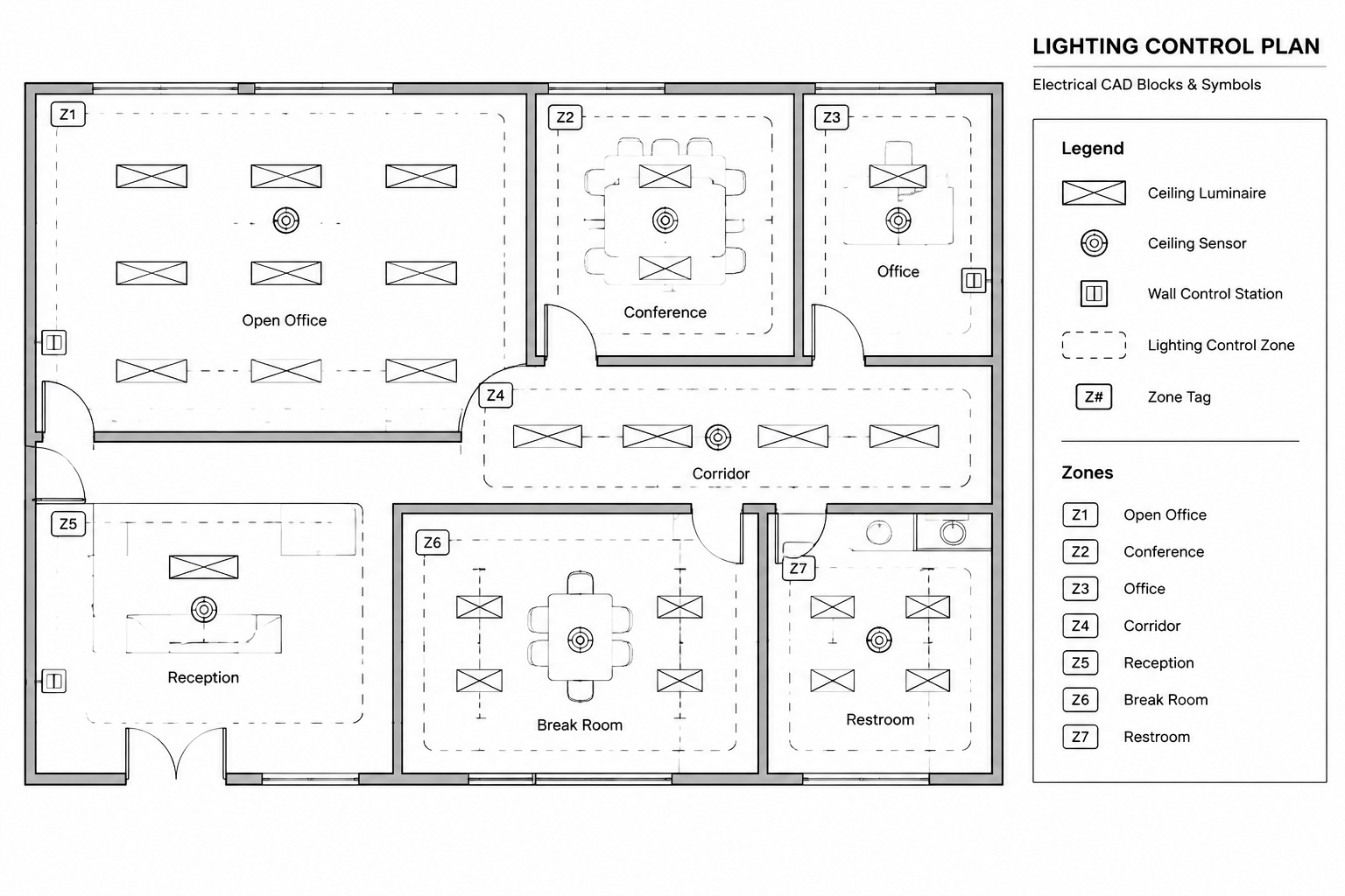
A lighting control plan explains more than the location of switches and sensors. It documents which luminaires are controlled together, what device provides the control, and how the intended operation relates to the lighting layout. When this information is incomplete, contractors and reviewers may have to infer connections from circuit lines, room boundaries, or fixture tags.
A well-organized lighting control plan in CAD separates control intent from physical wiring assumptions. It gives each control zone an identifiable reference, coordinates device symbols with the legend, and connects plans to schedules or diagrams without overloading the floor plan. The objective is not to show every conductor. It is to create a consistent design record that can be checked across the drawing set.
What a Lighting Control Plan Should Communicate
The lighting plan typically identifies luminaires, fixture types, circuiting, and related electrical information. The control plan adds the operational relationship between those luminaires and their control devices. Depending on the project documentation approach, the control information may appear on the lighting plan, on a separate control plan, or in a combined plan supported by diagrams and schedules.
At a minimum, the drawings should make the following relationships understandable:
- Which luminaires belong to each control zone.
- Which switches, sensors, stations, relays, or control interfaces affect that zone.
- Whether a device serves one zone or multiple zones.
- Whether the control is local, scheduled, automatic, networked, or coordinated with another system.
- Where additional operating information can be found.
- Which conditions require confirmation by the project designer or control-system provider.
The plan should document design intent without claiming that a generic symbol or CAD block defines the complete technical behavior of a real product.
Start with the Lighting Layout and Room Functions
Begin from a coordinated lighting layout rather than drafting control graphics in isolation. Review fixture locations, room names, ceiling conditions, architectural partitions, circulation paths, and special-use spaces. These references help determine where separate control zones need to be represented.
Room boundaries are useful organizational clues, but they should not automatically be treated as control boundaries. A large room may contain several zones, while luminaires in multiple small areas may share an operating relationship. Daylit areas, presentation areas, accent lighting, task lighting, circulation lighting, and after-hours lighting may also need to be distinguished graphically when they operate differently.
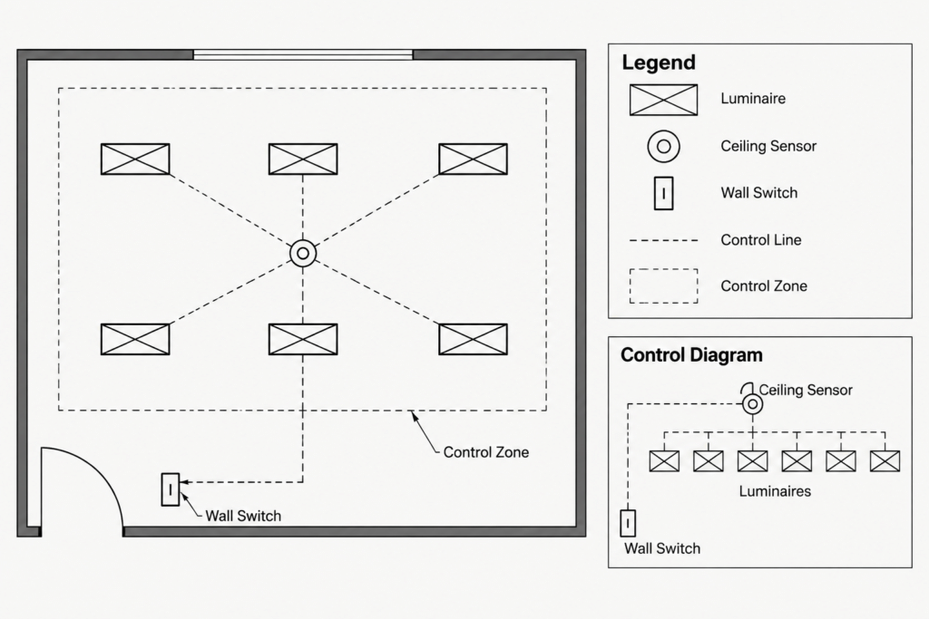
Before drawing control lines, create a simple working list of spaces, fixture groups, control methods, and unresolved questions. This prevents the CAD plan from becoming the first and only place where control decisions are recorded.
Assign Clear Control Zone Identifiers
A control zone is a group of luminaires intended to respond together to a particular command or operating condition. Give each zone a concise identifier that can be repeated on the plan, in schedules, and on diagrams. The identifier should remain stable as the drawing develops.
Zone tags should not be confused with fixture type tags, circuit references, switch designations, or room numbers. These identifiers serve different purposes. If the same text could reasonably be interpreted in more than one way, add a prefix, suffix, or legend explanation that makes its function clear.
Several graphic methods can identify a zone:
- A zone tag placed near the controlled luminaires.
- A light dashed boundary surrounding the fixture group.
- A control line connecting a device to a zone tag.
- A keynote pointing to a written control description.
- A reference to a control schedule or sequence diagram.
Use the method that remains readable at the intended plot scale. Avoid relying only on color because printed sets, grayscale plots, and exported files may not preserve color distinctions.
Choose a Consistent Graphic Language
Control graphics should be visually distinct from branch-circuit graphics, architectural linework, and fixture outlines. A dedicated CAD layer structure can help separate control devices, control relationships, zone boundaries, tags, and notes. Layer names should follow the project’s established CAD convention rather than introducing an unrelated system.
Control lines are usually diagrammatic. Unless the drawing explicitly states otherwise, they should not be interpreted as exact cable routes or conductor quantities. Include a legend note that explains what the line represents, especially when the same plan also contains circuiting or home-run graphics.
| Drawing element | Purpose | Coordination concern |
|---|---|---|
| Control device symbol | Shows the device category and approximate plan location | Coordinate with the symbol legend and device schedule |
| Zone tag | Identifies a controlled fixture group | Keep the identifier consistent across plans and diagrams |
| Control line | Shows a logical relationship | Do not let it appear to be a physical raceway route |
| Zone boundary | Clarifies the extent of a fixture group | Avoid obscuring ceiling, fixture, or room information |
| Sequence reference | Directs the reader to operating intent | Confirm that the referenced note or schedule exists |
Place and Tag Control Devices Carefully
Switches, dimming stations, occupancy-related sensors, daylight-related sensors, relay panels, and control interfaces may all appear on a lighting control plan. Use symbols that describe the device category without suggesting unverified product details. A generic sensor symbol, for example, should not imply a specific detection pattern or coverage area unless that information has been selected and documented.
Place wall-mounted device symbols in a consistent relationship to doors and walls so the drawing is easy to read. Coordinate their locations with architectural openings, casework, movable partitions, equipment, and other wall devices. Ceiling-mounted control devices should be coordinated with the reflected ceiling plan and nearby ceiling elements.
When a control station has multiple functions, avoid crowding small labels around the symbol. Assign a station tag and describe its functions in a control device schedule or keyed note. This keeps the plan legible while preserving the connection between location and operating intent.
Document the Sequence of Operation
A control line can show that a device affects a zone, but it may not explain what actually happens. The sequence of operation records behavior in plain language. It can describe manual commands, automatic responses, scheduled conditions, dimming relationships, overrides, and coordination with other systems.
Write sequences around observable outcomes rather than proprietary programming terms. For example, identify which zone responds to a device or condition and describe the intended state or adjustment. If timing, setpoints, or detailed programming criteria have not been confirmed, mark them for design coordination instead of inserting assumed values.
Complex spaces may benefit from a control matrix:
| Zone | Associated luminaires | Control input | Intended response | Drawing reference |
|---|---|---|---|---|
| Zone identifier | Fixture groups or area description | Station, sensor, schedule, or interface | Plain-language operating intent | Plan, note, schedule, or diagram reference |
The matrix structure helps reviewers find gaps, such as a zone without an input, a device without an assigned zone, or a sequence that references an untagged group.
Coordinate Plans, Schedules, and Diagrams
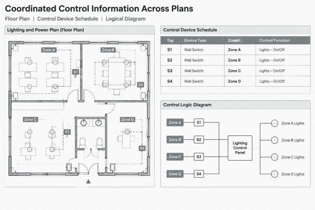
Lighting controls often appear in several drawing views. The floor plan shows spatial relationships, the schedule organizes device information, and a schematic or riser-style diagram may explain system relationships. These views should complement one another rather than repeat conflicting information.
Use the same device and zone identifiers everywhere. If a relay or control panel is tagged on the floor plan, that tag should match its schedule and diagram references. If the diagram groups multiple zones under a common controller, verify that every listed zone appears on the applicable plans.
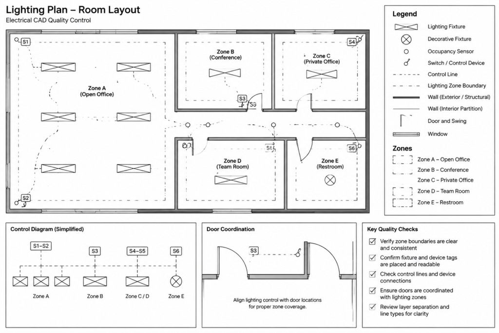
Also coordinate fixture schedules and lighting plans. A fixture type may support a particular control concept, but the CAD symbol alone cannot confirm compatibility. Product selections, control interfaces, emergency operation, and project-specific requirements must be verified by the responsible design team.
Handle Special Operating Conditions Explicitly
Some luminaires may have operating conditions that differ from the surrounding zone. Examples can include emergency-related lighting, night lighting, security coordination, or luminaires controlled through another building system. Do not leave these relationships to graphic inference.
Use a distinct tag, note, or diagram reference to identify the exception. Avoid modifying a common fixture symbol in subtle ways unless the legend clearly explains the variation. The plan should also distinguish between normal control intent and any condition governed by separate project criteria. Applicable requirements and equipment behavior must be verified for the actual project.
CAD Quality-Control Checks
Before issuing the drawings, perform a control-focused review rather than relying only on a general plan check. Useful checks include:
- Every control zone has a unique and readable identifier.
- Every shown control device is associated with a zone, function, note, or schedule entry.
- Zone tags match the control matrix, diagrams, and sequence descriptions.
- Control lines are distinguishable from circuiting and physical routing.
- Symbols match the legend and do not contain unexplained variations.
- Device locations are coordinated with doors, partitions, ceilings, and equipment.
- Unconfirmed programming details are identified for coordination rather than assumed.
- Special operating conditions are clearly separated from ordinary room control.
- Text, boundaries, and lines remain readable in the plotted output.
- Removed or revised zones no longer remain in schedules or diagrams.
A useful final test is to select one room and trace its control story from beginning to end: identify its luminaires, find the zone tag, locate the controlling devices, read the operating sequence, and confirm any schedule or diagram references. If that path is difficult for the drafting team to follow, it will also be difficult for other drawing users.
Keep Design Intent Separate from Installation Detail
The strongest lighting control drawings are clear about what they do and do not represent. They show logical relationships, locations, identifiers, and intended outcomes. They do not use generic CAD graphics as a substitute for verified equipment data, final programming, installation details, or project-specific engineering.
By coordinating zone tags, control symbols, schedules, and sequences, a lighting control plan becomes a reliable part of the electrical drawing set. It supports review and coordination while allowing detailed product and installation information to be verified through the appropriate project documents.




Leave a Reply
You must be logged in to post a comment.