
Fire alarm plans in CAD must connect physical device locations with system-level information distributed across plans, risers, schedules, details, and control documents. Clear symbols alone are not enough when tags, pathways, zones, addresses, and interface references are inconsistent between views.
The following drafting guide explains how to organize those relationships without crowding the floor plan or implying unverified installation details. It is intended as a documentation and coordination reference; project-specific design decisions must be confirmed through the applicable criteria, product information, and professional review.
Fire alarm plans combine location-based information with system relationships that may not be obvious from a floor plan alone. A detector symbol identifies a position, but the complete drawing package may also need to communicate its device address, initiating function, pathway association, control relationship, and connection to other building systems.
A reliable CAD workflow separates these different kinds of information while keeping them coordinated. The goal is not to place every possible note beside every symbol. It is to build a drawing set in which plans, riser diagrams, schedules, details, and control documentation support one another.
This guide focuses on drafting and documentation. Device selection, spacing, circuit design, survivability, power supplies, notification coverage, testing, and code compliance must be verified against the project criteria, applicable requirements, manufacturer documentation, and authority review.
Decide What Each Fire Alarm Drawing Will Communicate
Before drafting, assign a clear purpose to each drawing type. Overloading the floor plan with diagram-level information usually creates clutter without improving coordination.
| Drawing or document | Primary purpose | Typical coordinated information |
|---|---|---|
| Floor plan | Shows device and equipment locations | Symbols, tags, room relationships, pathway intent, interface locations, and local notes |
| Riser diagram | Shows system architecture | Panels, remote units, loops, circuits, network links, levels, and major interfaces |
| Device schedule | Organizes device data | Tag, type, location, function, circuit or loop reference, and remarks |
| Sequence or matrix | Documents cause-and-effect relationships | Initiating events, outputs, releases, shutdowns, supervision, and annunciation |
| Installation detail | Clarifies a repeated condition | Mounting context, coordination limits, connection intent, and referenced notes |
This division helps reviewers find information quickly. It also reduces the risk of maintaining the same technical statement in several unrelated locations.
Build a Controlled Symbol and Tagging System
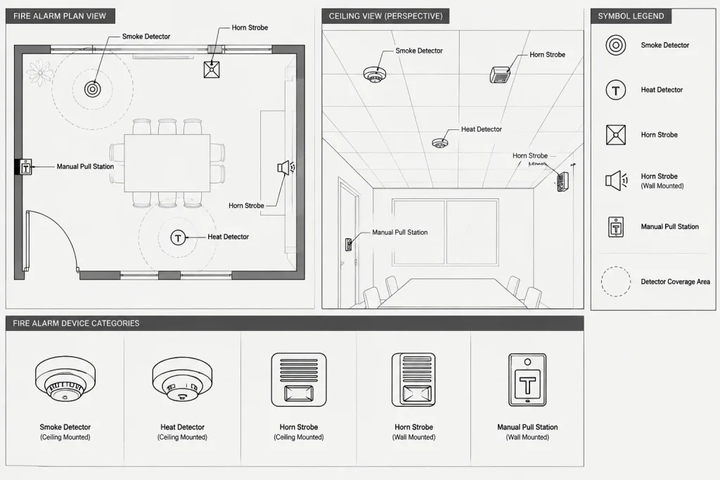
A fire alarm symbol should identify a device category without pretending to define every product characteristic. Use separate symbols where the visual distinction is important to plan reading, but avoid creating nearly identical blocks for minor specification differences that belong in a schedule.
Define symbols by drawing purpose
Plan symbols commonly represent initiating devices, notification appliances, control modules, monitor modules, manual stations, annunciators, control equipment, and system interfaces. Diagram symbols may represent the same devices differently because a riser emphasizes connectivity rather than physical footprint.
Do not assume that a plan symbol can be reused unchanged in every view. A symbol family can include coordinated plan, elevation, detail, and diagram representations while retaining a shared device identifier.
Use attributes selectively
Useful block attributes may include:
- A unique device tag
- A device type or schedule key
- A circuit, loop, or pathway reference
- A zone or area reference where the project uses one
- A mounting or coordination note reference
- A status field for existing, new, relocated, or removed work
Keep attributes separate from the symbol graphics. This allows text to be moved, rotated, or hidden for a particular viewport without changing the device itself. Attribute visibility should be controlled by a documented office workflow rather than by exploding blocks.
Place Devices Against a Reliable Background
Begin with a controlled architectural underlay that includes current rooms, doors, ceilings, partitions, and relevant equipment. Fire alarm device locations are frequently affected by architectural and reflected ceiling information, so background updates must be reviewed rather than accepted as passive file changes.
During placement, look for documentation conflicts such as:
- Devices located in rooms that were renamed, divided, or removed
- Ceiling-mounted symbols that no longer align with the ceiling layout
- Wall devices placed where doors, casework, or equipment interfere with the intended location
- Duplicate symbols created during background revisions
- Devices copied between similar rooms without updated tags
- Interface modules separated visually from the equipment they serve
The CAD plan should show design intent clearly, but it should not imply that an approximate symbol center is a verified installation coordinate. Use dimensions, elevations, details, or specific notes only when the project team has established and checked that information.
Separate Device Locations from Pathway Intent
Fire alarm plans often need to indicate pathways between devices, but linework can easily be mistaken for exact routing. Establish a graphic convention that tells readers whether a line represents circuit grouping, general routing intent, or a coordinated raceway path.
Pathway linework should remain visually subordinate to devices and tags. It should also be distinguishable from architectural lines, other low-voltage systems, and electrical branch circuiting. Where different pathway types must be identified, use a controlled combination of layers, linetypes, labels, and legend entries rather than color alone.
Avoid false connectivity
At crossings, make connected and unconnected conditions unambiguous. Do not rely on a crowded intersection that could be interpreted either way. Use documented junction notation, line breaks, offsets, or separate diagram views as appropriate to the project convention.
When pathways continue beyond a plan boundary, use a continuation reference that points to the correct sheet, area, riser, or system segment. A line disappearing at a match line or viewport edge without a reference creates an unresolved circuit.
Coordinate Zones, Loops, Circuits, and Addresses
Zone, loop, circuit, and address are not interchangeable terms. Their exact use depends on the system architecture and project documentation method. The CAD standard should define each field before tags are populated.
A practical data structure might distinguish:
- Device ID: the unique identifier used across plans and schedules
- Device type: the symbol or scheduled category
- System segment: the relevant loop, circuit, network, or pathway grouping
- Address: a project-assigned identifier when applicable and confirmed
- Area or zone: a functional or reporting group when used by the design
- Interface reference: a link to a sequence, matrix, equipment tag, or control detail
Keeping these fields separate prevents a single text string from becoming difficult to revise. It also supports exports to schedules or checking tools without requiring the drafter to parse combined labels.
Document Building-System Interfaces Explicitly
Many of the most important fire alarm drawing relationships occur at interfaces with other systems. Examples may include elevator controls, air-handling equipment, smoke control functions, door release arrangements, suppression-system monitoring, emergency communication functions, security coordination, and remote annunciation.
A floor plan should identify the physical interface location when known. A riser or interconnection diagram should show the relationship between systems. A sequence or matrix should explain the intended response. These documents must use the same equipment tags and function names.
A vague note such as “connect to mechanical equipment” is difficult to coordinate. A stronger documentation approach identifies the served equipment, references the associated interface or module, and directs the reader to the drawing where the control relationship is defined. The drawing should also make scope boundaries visible when hardware, programming, wiring, or final connections are assigned to different parties.
Coordinate Plans with the Fire Alarm Riser
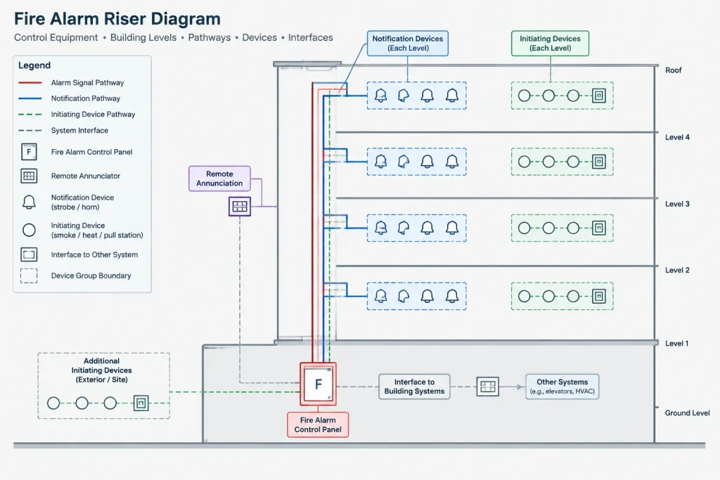
The riser is not merely a simplified copy of the plan. It provides a system-level view that can reveal missing segments, inconsistent circuit names, and unclear equipment relationships.
Use a repeatable reconciliation process:
- Confirm that each major control unit or annunciation point shown on plans appears on the riser where applicable.
- Compare plan pathway labels with riser labels.
- Check that every level or building area has a clear system relationship.
- Verify that interface devices appear in the relevant plans, diagrams, and schedules.
- Resolve plan continuations that have no corresponding destination.
- Review whether spare, future, existing, and removed conditions are represented consistently.
The riser should communicate architecture without implying unverified internal product construction. Product-specific terminal assignments and connection requirements belong in verified manufacturer or shop documentation unless they are explicitly part of the project drawing scope.
Use Layers to Support Review, Not to Encode the Entire Design
A manageable layer structure might separate device categories, pathway linework, tags, notes, interface graphics, demolition information, and backgrounds. Additional separation can be useful when it supports plotting or discipline coordination, but creating a layer for every device subtype often produces unnecessary complexity.
Layer names should remain stable across plans. If status is important, decide whether it will be represented by dedicated layers, block properties, attributes, or a controlled combination. Avoid ad hoc object overrides that make two devices on the same layer plot differently without an obvious reason.
Run a Focused Fire Alarm Drawing Review
Before publishing, review the set both graphically and as coordinated data.
Graphic review
- Confirm that symbols remain readable over the background.
- Move overlapping tags without separating them visually from their devices.
- Check line crossings and continuation points.
- Verify that screened backgrounds do not hide pathways or symbols.
- Inspect enlarged or rotated viewports for inconsistent annotation orientation.
Coordination review
- Search for duplicate and missing device identifiers.
- Compare symbols against the legend and device schedule.
- Reconcile plan labels with riser segments.
- Check interface references against equipment tags and the sequence documentation.
- Confirm that room names and level references match the current architectural files.
- Review revision clouds and change markers against the actual drawing changes.
A final plotted or PDF review is essential because layer visibility, masks, lineweights, and viewport settings can produce problems that are not apparent in model space.
Make the Drawing Set Traceable
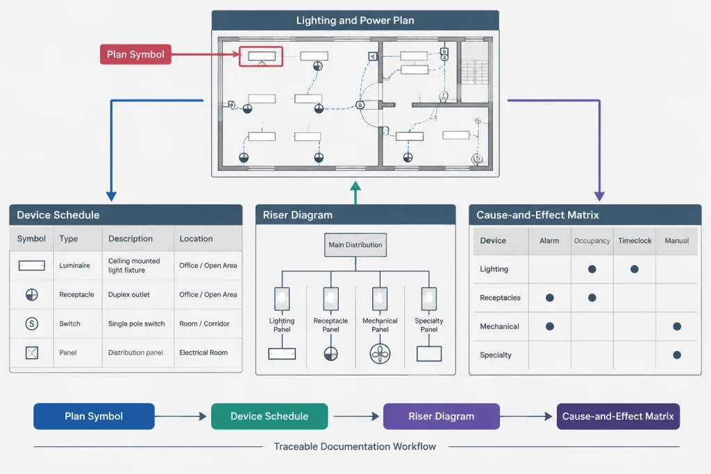
Good fire alarm CAD documentation allows a reviewer to follow a device from its physical location to its system relationship and intended function. That trace may begin with a plan symbol, continue through a device schedule and riser, and end at an interface matrix or referenced detail.
The strongest workflow does not force every answer onto one sheet. It gives each document a defined role, applies consistent identifiers, and provides clear references between views. With that structure in place, CAD blocks become more than isolated symbols: they become coordinated records within the drawing set.
Establish Information Ownership Across the Drawing Set
Coordination becomes easier when the project team identifies which document controls each type of information. The floor plan may control the displayed location, the riser may control the system relationship, the schedule may control descriptive device data, and the sequence documentation may control the stated response to an initiating event.
This ownership does not make the documents independent. It establishes where a disputed value should be verified before related references are updated. Without that hierarchy, drafters may correct a tag on the plan while leaving a conflicting schedule entry or riser label unchanged.
Use a controlled correction workflow
- Identify whether the conflict concerns location, identity, connectivity, status, or system function.
- Confirm the document or approved data source responsible for that information.
- Update dependent tags, schedules, diagrams, and references together.
- Check that the correction did not create a duplicate identifier or an unresolved continuation.
- Review the plotted output rather than relying only on model-space visibility.
Preserve Meaning During CAD Revisions
A background revision can move a symbol without changing its system assignment, while a design revision can change the assignment without moving the symbol. Treat these as different events. Comparing graphics alone may not reveal changes to attributes, schedule fields, pathway references, or interface relationships.
For revision handoff, record which drawing relationships were reviewed and which remain pending confirmation. Clearly distinguish incomplete coordination from intentionally reserved, future, existing, relocated, or removed conditions. This prevents temporary drafting assumptions from appearing to be finalized design information.
Test Traceability with a Sample Device
A practical quality check is to select a representative device or interface and follow it through every applicable document. Its identifier, type, location, pathway association, schedule record, riser relationship, and control reference should describe the same design intent.
If that trace cannot be completed without guessing, the set needs a clearer identifier, continuation reference, legend entry, or document cross-reference. This check is especially useful after architectural updates, system restructuring, or imported schedule changes.
Frequently Asked Questions About Fire Alarm CAD Plans
What should a fire alarm floor plan show?
A floor plan generally communicates device and equipment locations, identifying tags, room relationships, pathway intent, interface locations, and relevant local notes. System architecture and cause-and-effect information are usually clearer in coordinated risers, schedules, and sequence documents.
Are zones, loops, circuits, and addresses the same thing?
No. These terms describe different forms of system grouping or identification, and their use depends on the project architecture. CAD fields should remain separate so revisions can be made without rebuilding combined labels.
Should pathway lines represent exact routing?
Only when the drawing convention and project information explicitly establish coordinated routing. Otherwise, the legend and notes should clarify whether linework represents grouping, connectivity, general routing intent, or another documented relationship.
How should fire alarm interfaces be documented?
Use consistent equipment and interface identifiers across the floor plan, riser or interconnection diagram, schedule, and sequence documentation. The drawing set should also make scope boundaries visible without assuming unverified wiring, programming, or terminal details.
Why use separate plan and riser symbols?
A plan emphasizes physical location, while a riser emphasizes system connectivity. Coordinated symbol representations can share the same device identifier without using identical graphics in every drawing type.
What is a useful final CAD quality check?
Trace representative devices from their plan locations through the applicable schedules, risers, details, and control references. Then review the plotted or exported sheets for hidden linework, tag conflicts, masking problems, and inconsistent viewport settings.

Leave a Reply
You must be logged in to post a comment.