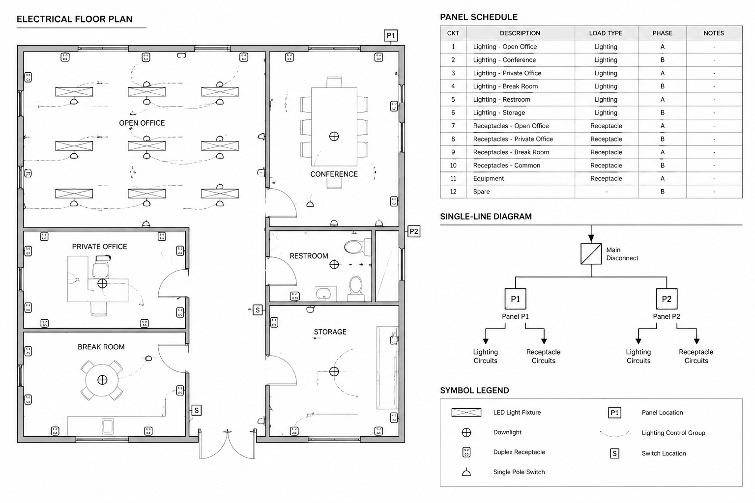
Electrical circuit numbering in CAD is more than adding a number beside a receptacle or lighting fixture. A circuit identifier connects information across floor plans, panel schedules, single-line diagrams, equipment schedules, and sometimes control drawings. If that identifier is missing, inconsistent, or difficult to revise, the drawing set becomes harder to review and maintain.
A reliable workflow treats circuit information as coordinated project data rather than isolated annotation. The exact circuit assignments must come from the project design and verified schedules, but CAD standards can make those assignments easier to display, check, and revise.
What a Circuit Tag Communicates
A circuit tag generally identifies the source serving a device, fixture, equipment connection, or group of loads. Depending on the office standard and drawing type, the displayed information may include a panel designation, circuit reference, system abbreviation, or other project-specific qualifier.
These elements should not be combined casually. A panel designation identifies the source equipment, while the circuit reference identifies a position or assignment associated with that source. A system tag may instead identify normal power, standby power, emergency power, control power, or another documented distribution category. The drawing legend and schedules should make the intended meaning clear.
Before drafting circuit tags, determine:
- Which source designation appears on the plan.
- Whether the circuit reference is shown separately or as part of a combined tag.
- How multi-circuit and multi-pole connections are represented.
- Whether switched or controlled loads need an additional control identifier.
- How spare, future, or unassigned conditions are documented.
- Which drawing or schedule is the controlling source for assignments.
Where Circuit Information Appears
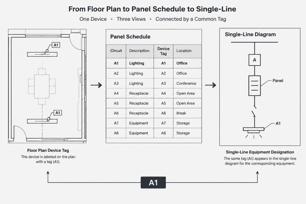
Circuit assignments can appear in several drawing locations, but each location serves a different purpose. Coordination does not require every sheet to repeat all available information. It requires each representation to agree with the others.
| Drawing location | Primary purpose | Common coordination risk |
|---|---|---|
| Power plan | Connects outlets and equipment to a documented source | Tags do not match the panel schedule |
| Lighting plan | Identifies fixture circuiting and its relationship to controls | Circuit and control identifiers are confused |
| Panel schedule | Records organized circuit assignments and load descriptions | Plan revisions are not transferred to the schedule |
| Single-line diagram | Shows distribution relationships between source equipment | Panel names differ from plan designations |
| Equipment schedule | Documents source and connection information for scheduled equipment | Equipment tags or source fields are outdated |
| Details and diagrams | Clarify a typical or specialized connection | A typical note is mistaken for a final project assignment |
Build a Consistent Tag Format
A circuit tag should be compact enough for a crowded plan but clear enough to interpret without guesswork. Use a consistent order for panel and circuit information throughout the project. Do not reverse that order on different sheets unless the legend clearly defines separate conventions.
Visual separators can improve readability. A dash, slash, stacked arrangement, or leader-based annotation may be appropriate, but the selected format should match the project CAD standard. Avoid relying only on text color because color may disappear in monochrome plots, scans, or exports.
Separate Circuiting from Other Identifiers
Electrical plans often place several identifiers near the same symbol. A receptacle may have a device type, mounting note, circuit tag, and keyed note. A luminaire may have a fixture type, circuit designation, switching reference, and control-zone tag. These labels should have distinct graphic roles.
For example, fixture types can use one enclosure style, circuit tags another, and control references a third. Consistent positioning also helps: circuit data may occupy a predictable side of the symbol while equipment or fixture types occupy another. The arrangement should remain readable when symbols rotate or occur near walls and architectural notes.
Use CAD Data Instead of Uncontrolled Text
Plain text can work for a small drawing, but repeated manual labels are vulnerable to transcription errors. A more controlled CAD workflow uses attributed blocks, structured annotation objects, or another office-approved data method. The objective is not automation for its own sake; it is to keep the displayed tag connected to editable fields.
Useful fields may include:
- Source panel designation.
- Circuit reference.
- System or distribution category.
- Associated equipment or device identifier.
- Sheet or detail reference when required.
- A review status or temporary coordination note kept on a non-plotting layer.
Field names should be understandable to other team members. Avoid cryptic attribute prompts that force users to remember undocumented abbreviations. If a block supports several optional fields, configure its default display so unused data does not leave stray punctuation or empty enclosures.
Coordinate the Plan with the Panel Schedule
The panel schedule and floor plan should be reviewed as a pair. Every final circuit tag shown on the plan should point to an identified source, and every active schedule entry should have a description that can be reconciled with the documented loads. That does not mean every schedule description must repeat room names or plan notes word for word. It means the relationship should be traceable.
A practical review sequence is:
- Confirm that the panel designation exists and is spelled consistently.
- Compare each plan circuit tag with the corresponding schedule assignment.
- Check that equipment identifiers agree between plans and schedules.
- Review grouped devices and home-run graphics for ambiguous coverage.
- Identify duplicated assignments that may have resulted from copied annotation.
- Flag blank, temporary, or unresolved tags before plotting.
Do not infer missing circuit assignments from nearby devices simply because they appear similar. A qualified project team member should resolve incomplete design information, after which the verified assignment can be entered into the drawings.
Check the Distribution Path on the One-Line Diagram
A floor-plan circuit reference usually points to a panel or similar source, while the one-line diagram explains where that source sits within the broader distribution system. The circuit tag itself does not need to reproduce the upstream path, but the source designation must match.
When checking the one-line, look for renamed panels, repeated identifiers, and equipment shown on one drawing but omitted from another. Also verify that normal, alternate, or specialized distribution paths are not represented by indistinguishable tags. If the one-line uses an equipment naming convention, the plans and schedules should follow the same convention unless a documented translation is provided.
Handle Home Runs and Grouped Devices Carefully
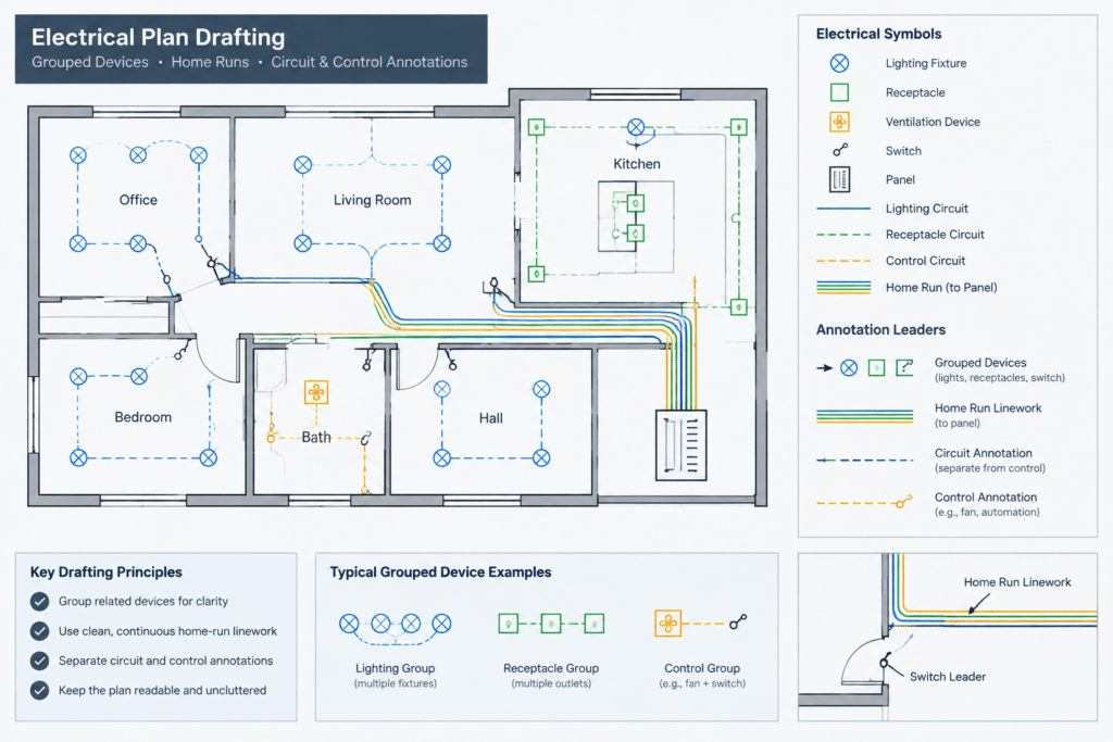
A home-run line is a graphic shorthand, not a substitute for clear scope. When several devices are connected graphically, the reader must be able to determine which devices belong to the indicated circuit or circuits. Overlapping linework, long chains, and crowded branches can make that relationship uncertain.
Keep circuit graphics subordinate to devices and architectural information, but visible enough to trace. Break or reroute lines around text rather than drawing through tags. Where continuation is necessary, use a defined reference method and make sure both ends agree. If multiple circuits follow a common path, label them according to the project convention instead of stacking unrelated text along the line.
Plan for Circuit Renumbering and Revisions
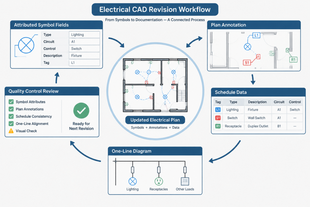
Circuit assignments often change as panel schedules are balanced, equipment is revised, or drawing backgrounds develop. A good CAD structure makes those changes manageable.
Avoid embedding circuit numbers inside unrelated device geometry. Keep attributes editable, and use dedicated layers for circuit annotation and circuit linework. If schedules are produced separately from the CAD plan, establish a formal comparison step rather than assuming both documents remain synchronized automatically.
During revisions, search for every occurrence of the affected panel and circuit reference. The same assignment may appear in a plan tag, schedule entry, equipment connection table, detail note, or continuation callout. Revise the full documentation chain, then remove temporary clouds or review notes according to the project issue workflow.
Common Circuit-Numbering Errors
- Copied tags: A device is copied to a new location while retaining the previous assignment.
- Panel-name drift: Abbreviations differ between the plan, schedule, and one-line.
- Ambiguous leaders: A tag appears between devices without clearly identifying which symbol it serves.
- Control confusion: A lighting control-zone identifier is mistaken for a branch-circuit reference.
- Hidden information: Tags are placed on frozen, non-plotting, or incorrectly filtered layers.
- Stale references: Circuit assignments remain in details or schedules after the plan changes.
- Unreadable stacking: Panel, circuit, fixture, and control data overlap at the plotted scale.
Final CAD Review Checklist
Before issuing the drawings, perform both a data check and a plotted-sheet check. Database accuracy does not guarantee readable graphics, and a clean plot does not guarantee that the assignments are correct.
- Confirm that tag formats match the legend and project standard.
- Verify panel names across plans, schedules, diagrams, and equipment tables.
- Check circuit assignments against the current verified schedule.
- Review leaders, home runs, and grouped devices for clear association.
- Confirm that circuit text plots at the intended sheet scale.
- Look for empty attributes, placeholder text, and unresolved coordination notes.
- Search for superseded panel names and circuit references.
- Verify that revisions were applied everywhere the affected assignment appears.
Clear electrical circuit numbering in CAD depends on disciplined coordination, not just a well-drawn tag. When plans, panel schedules, one-lines, and related tables use consistent source designations and controlled annotation, the drawing set becomes easier to navigate, review, revise, and use as a technical record.

Leave a Reply
You must be logged in to post a comment.